Injection device for supporting and lifting ligament
A technology for injection devices and ligaments, which is applied in the direction of syringes, hypodermic injection devices, and devices introduced into the body, etc. It can solve the problems of difficult injection of drugs for ligament lifting, and achieve the effect of reducing the difficulty of injection and avoiding damage
- Summary
- Abstract
- Description
- Claims
- Application Information
AI Technical Summary
Problems solved by technology
Method used
Image

Examples
Embodiment 1
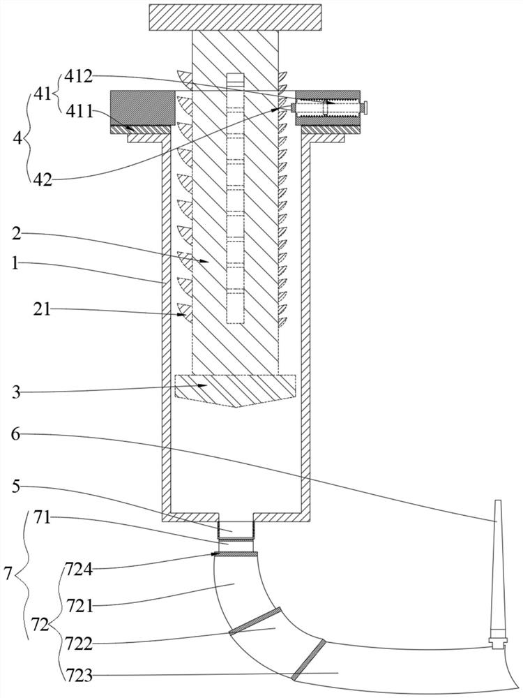
[0052] An injection device for ligament support lifting, comprising:
[0053] The drug storage unit, the drug storage unit includes an injection tube 1, an injection push rod 2, an injection piston 3 and a rotating grading part 4; the injection push rod 2 is set in the injection tube 1, and the end of the injection push rod 2 is fixedly connected to the injection piston 3, The injection piston 3 abuts against the inner wall of the injection tube 1, and the injection push rod 2 is provided with several sliding racks 21, which are arranged on the side wall of the injection push rod 2 and extend along the axial direction of the injection push rod 2; The pitches of each sliding rack 21 are different;
[0054] The rotation grading part 4 includes a rotation locking mechanism 41 and an elastic piece 42, the rotation locking mechanism 41 is fixed on the inlet end of the injection tube 1, the elastic piece 42 is fixed on the rotation locking mechanism 41, and the elastic piece 42 abut...
Embodiment 2
[0057] Compare embodiment 2 and embodiment 1, the difference of embodiment 2 and embodiment 1 is only:
[0058] In order to ensure the fixing and separating effect of the rotation locking mechanism 41 on the elastic piece 42, the application also makes detailed settings for the rotation classification part 4, the details are as follows:
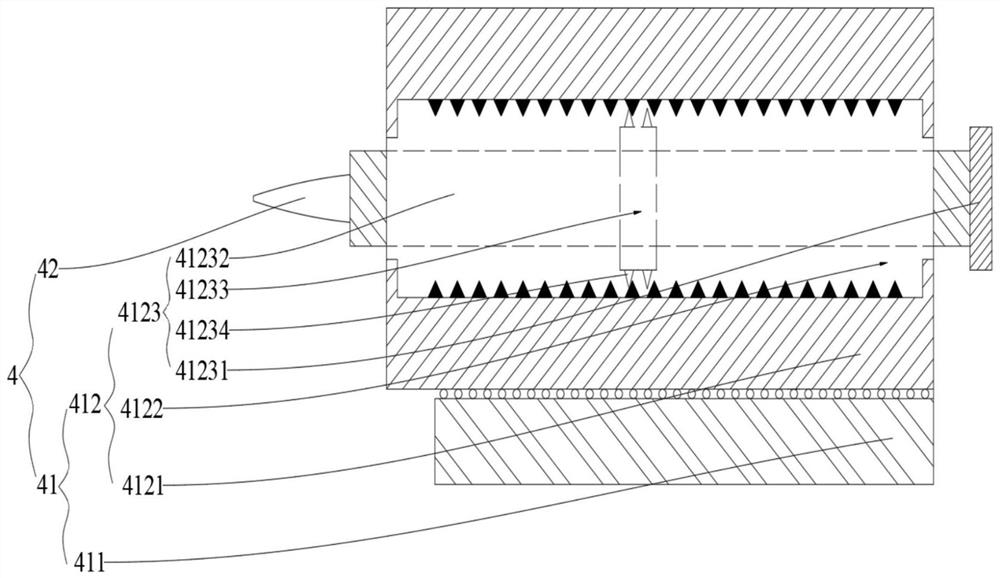
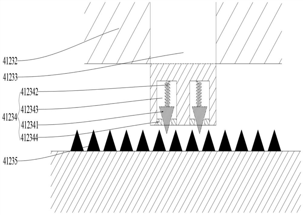
[0059] The rotation locking mechanism 41 includes a rotating disk 411 and a fixing mechanism 412. The rotating disk 411 is fixed on the inlet end of the injection tube 1. The fixing mechanism 412 includes a fixed shell 4121, a locking hole 4122 and an elastic locking part 4123. The fixed shell 4121 is rotatably connected to the rotating disk 411. , the locking hole 4122 penetrates the side wall of the fixed housing 4121 , the elastic locking portion 4123 is disposed in the locking hole 4122 , and one end of the elastic locking portion 4123 is fixedly connected to the elastic piece 42 .
[0060] At the same time, in order to ensure that the el...
Embodiment 3
[0064] Compare embodiment 3 and embodiment 1, the difference of embodiment 3 and embodiment 1 is only:
[0065] In order to further improve the accuracy of locating the facial ligaments, the application also limits the length of the arc-shaped catheter, which specifically includes: the injection catheter 7 includes a straight catheter 71 and three sections of arc-shaped catheter 72 connected in sequence, and the three-section arc-shaped catheter 72 comprises in turn the first section of arc duct 721, the second section of arc duct 722 and the third section of arc duct 723; the axial length of the first section of arc duct 721 along the straight duct 71 is L1, and the second section of arc duct The axial length of the arc-shaped conduit 722 along the straight conduit 71 is L2, and the axial length of the third arc-shaped conduit 723 along the straight conduit 71 is L3.
[0066] In order to further improve the rationality of positioning, L1:L2:L3=5:8:6, so that by setting the le...
PUM
 Abstract
Description
Claims
Application Information
 - R&D Engineer
- R&D Manager
- IP Professional
- Industry Leading Data Capabilities
- Powerful AI technology
- Patent DNA Extraction
Browse by: Latest US Patents, China's latest patents, Technical Efficacy Thesaurus, Application Domain, Technology Topic.
© 2024 PatSnap. All rights reserved.Legal|Privacy policy|Modern Slavery Act Transparency Statement|Sitemap