Forearm medicine spraying equipment for burn department
A technology of equipment and nozzles, applied in the field of forearm spraying equipment in the department of burns, can solve the problems of secondary injury and immobilization of the patient's arm, and achieve the effect of preventing secondary injury, increasing injury, and achieving good results.
- Summary
- Abstract
- Description
- Claims
- Application Information
AI Technical Summary
Problems solved by technology
Method used
Image
Examples
Embodiment 1
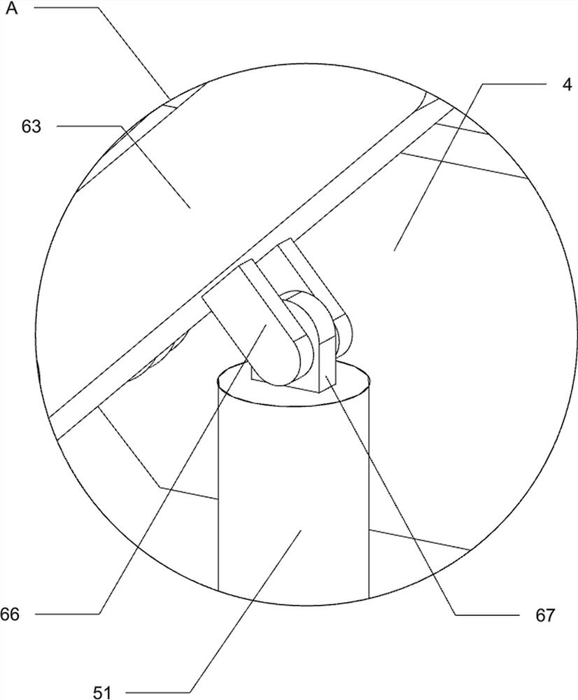
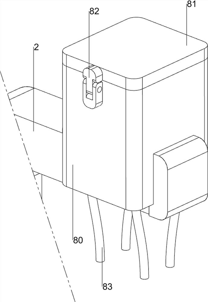
[0027] A kind of small arm medicine spraying equipment in burn department, such as Figure 1 to Figure 3 As shown, it includes a suction cup 1, a first mounting bracket 2, a medicine rack 3, a nozzle 4, a cartridge 5, a first hose 6, an air cylinder 7, a drug delivery mechanism 8 and a disinfection mechanism 9, and the first mounting bracket 2 The left and right sides of the bottom are symmetrically provided with suction cups 1, the top of the first mounting bracket 2 is provided with a medicine rack 3, and the top of the medicine rack 3 is provided with guide rails symmetrically front and back, and the nozzles 4 are arranged symmetrically on the guide rails. 4. The top is provided with a cartridge 5, the outside of the spray head 4 is connected with a first hose 6, and the left and right sides of the top of the drug rack 3 are symmetrically equipped with an air cylinder 7, and the air cylinder 7 is connected to the first hose on the same side respectively. 6 is connected and ...
Embodiment 2
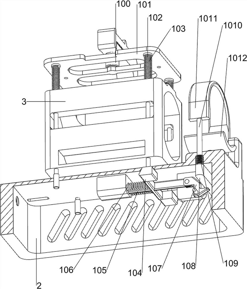
[0032] On the basis of Example 1, such as figure 1 , Figure 4 and Figure 5As shown, a clamping mechanism 10 is also included, and the clamping mechanism 10 includes a cylinder 100, a lower pressing plate 101, a first connecting rod 102, a first spring 103, a block 104, a moving rod 105, a second spring 106, a special-shaped block 107, connecting block 108, the third spring 109, the second connecting rod 1010, U-shaped block 1011 and hand rest 1012, the left and right sides of the top of the medicine rack 3 are all front and rear symmetrically slidingly provided with the first connecting rod 102, the first connecting rod 102 The rods 102 all pass through the tops of the first mounting bracket 2, the tops of the first connecting rods 102 are connected with the lower pressing plate 101, and the first connecting rods 102 and the tops of the upper medicine rack 3 are connected with the first springs 103. The rear side of the top of the support 2 is connected with a cylinder 100...
Embodiment 3
[0036] On the basis of Example 2, such as figure 1 , Figure 6 and Figure 7 Shown, also comprise hand-held mechanism 12, hand-held mechanism 12 comprises screw mandrel 120, adjustment button 121, moving block 122 and first handle 123, and the left side rotation type of first mounting bracket 2 is provided with screw mandrel 120, and The left side of the rod 120 is provided with an adjusting button 121 , the top left side of the first mounting bracket 2 is slidingly provided with a moving block 122 , the left side of the moving block 122 is threadedly connected with the screw rod 120 , and the top of the moving block 122 is provided with a first handle 123 .
[0037] Also include tool temporary storage mechanism 13, tool temporary storage mechanism 13 includes material storage tray 130, rotating shaft 131 and second handle 132, upper medicine rack 3 lower front side sliding type is placed with storage tray 130, before storage tray 130 The side-rotating type is provided with ...
PUM
 Abstract
Description
Claims
Application Information
 - R&D
- Intellectual Property
- Life Sciences
- Materials
- Tech Scout
- Unparalleled Data Quality
- Higher Quality Content
- 60% Fewer Hallucinations
Browse by: Latest US Patents, China's latest patents, Technical Efficacy Thesaurus, Application Domain, Technology Topic, Popular Technical Reports.
© 2025 PatSnap. All rights reserved.Legal|Privacy policy|Modern Slavery Act Transparency Statement|Sitemap|About US| Contact US: help@patsnap.com


