Angle grinder system

An angle grinder and motor technology, which is applied in the directions of grinding machine parts, grinding machines, grinding workpiece supports, etc., can solve the problems of saw blades and cutting blades splintered and splashed, unable to cut hard materials, and the machine bounces out of control. , to achieve the effect of convenient replacement work, stable processing work and stable processing process

Inactive Publication Date: 2022-04-08
殷玉柱
View PDF0 Cites 0 Cited by
  • Summary
  • Abstract
  • Description
  • Claims
  • Application Information

AI Technical Summary

Problems solved by technology

[0002] The electric angle grinder uses high-speed rotating sheet grinding wheels, rubber grinding wheels, wire wheels, etc. to grind, cut, derust, and polish metal components. The angle grinder is used for grinding, because the angle grinder has a high speed. When using cutting blades or saw blades, do not turn dead corners when cutting blades, or use too much force, and cannot cut hard materials thicker than 20mm through the through hole, otherwise, once stuck, the saw blades and cutting blades will be broken and splashed, or the machine will bounce. If the drive is out of control, it may damage the items, and even cause casualties. The machine cannot cut and replace the grinding wheel independently, and manual operation or replacement is required.

Method used


Image

  • Angle grinder system
  • Angle grinder system
  • Angle grinder system

Examples


Embodiment Construction

[0028] In order to make the purpose and advantages of the present invention clearer, the present invention will be described in detail below in conjunction with the examples. It should be understood that the following words are only used to describe an angle grinder system or several specific implementations of the present invention, and are not intended to Strictly defining the scope of protection specifically claimed by the present invention, as used herein, the terms up-down and left-right are not limited to their strict geometric definitions, but rather include reasonable and inconsistent tolerances for machining or human error, as detailed below Specific features of this one angle grinder system:

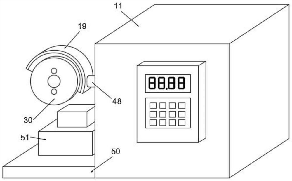
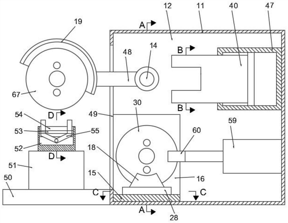
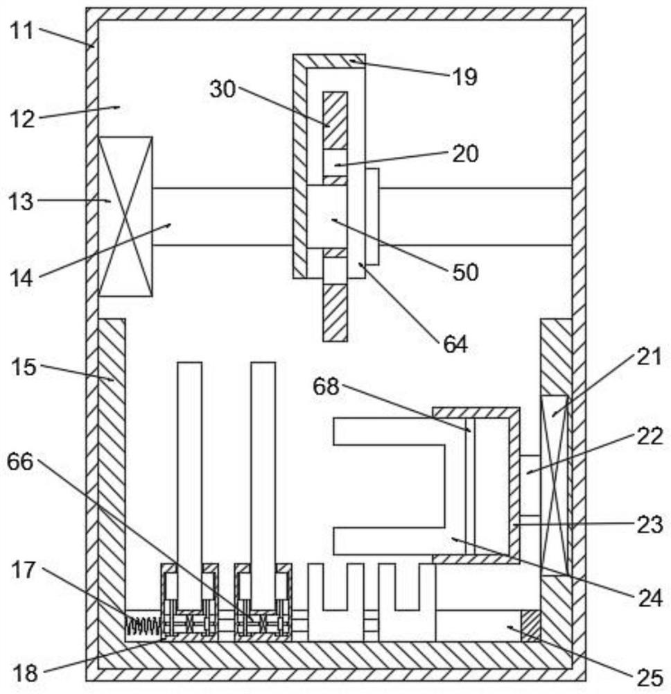
[0029] Refer to attached Figure 1-Figure 8 , an angle grinder system according to an embodiment of the present invention, comprising a housing 11, the housing 11 is provided with a working chamber 12, and the left wall of the working chamber 12 is provided with an opening 49 p...


PUM


Abstract

The angle grinder system comprises a shell, a working cavity is formed in the shell, an opening penetrating through the left end face of the shell is formed in the left wall of the working cavity, a U-shaped mounting block is fixedly arranged on the bottom wall of the working cavity, a U-shaped cavity is formed in the U-shaped mounting block, and a strip-shaped mounting block is fixedly arranged on the bottom wall of the U-shaped cavity; by arranging the clamping mounting block, the U-shaped connecting block and the locking connecting block, a workpiece can be locked, the grinding wheel is used for cutting and grinding, the U-shaped connecting block extends into the through hole to drive the grinding wheel to rotate to be loosened or connected with the threaded mounting block, new and old replacement of the grinding wheel is achieved, and the beneficial effects of being high in machining precision and convenient and fast to replace are achieved. And the wedge-shaped block, the abutting block and the threaded mounting block are further arranged, the grinding wheel can be fixed when the workpiece is cut, the machining process is stable, the machining surface is smooth, waste components can be replaced through connection of the threaded mounting block and the grinding wheel, and the beneficial effects that machining work is stable, and the working efficiency is improved are achieved.

Description

technical field [0001] The invention relates to the technical field of angle grinders, in particular to an angle grinder system. Background technique [0002] The electric angle grinder uses high-speed rotating sheet grinding wheels, rubber grinding wheels, wire wheels, etc. to grind, cut, derust, and polish metal components. The angle grinder is used for grinding, because the angle grinder has a high speed. When using cutting blades or saw blades, do not turn dead corners when cutting blades, or use too much force, and cannot cut hard materials thicker than 20mm through the through hole, otherwise, once stuck, the saw blades and cutting blades will be broken and splashed, or the machine will bounce. If it is out of control, it may damage items, and even cause casualties. It cannot make the machine cut and replace the grinding wheel independently, and manual operation or replacement is required. Contents of the invention [0003] The object of the present invention is to ...

Claims


Application Information

Patent Timeline
Patent Type & Authority Applications(China)
IPC IPC(8): B24B19/00B24B41/00B24B41/04B24B41/06B24B45/00
Inventor 殷玉柱
Owner 殷玉柱
Why Eureka
Try Eureka