
3D ceramic printer

A printer and ceramic technology, applied in the field of ceramic production equipment, can solve the problems of no sealing, the equipment cannot be widely used, and the ceramic printing cannot be realized.

Pending Publication Date: 2022-04-08
QUANZHOU KUNTAI MACHINERY PRECISION MFG CO LTD
View PDF0 Cites 0 Cited by
  • Summary
  • Abstract
  • Description
  • Claims
  • Application Information

AI Technical Summary

Problems solved by technology

In some existing documents, although there are a small number of records of 3D ceramic printing equipment, the 3D ceramic printing equipment recorded is basically made of mud, which is directly transported to the print head through the pump on the pipeline. For ceramic printing equipment, the prepared mud is completely exposed to the air without sealing or moisturizing. The prepared mud must be used and printed immediately, otherwise it will become dry in a short time and cannot be used. It requires a highly compact preparation process, otherwise it will not be possible to print ceramics, this reason is also leading to the large-scale promotion and use of this equipment

Method used


Image

  • 3D ceramic printer
  • 3D ceramic printer
  • 3D ceramic printer

Examples


Embodiment Construction

[0029] A preferred embodiment of the 3D ceramic printer of the present invention will be described in detail below in conjunction with the accompanying drawings:

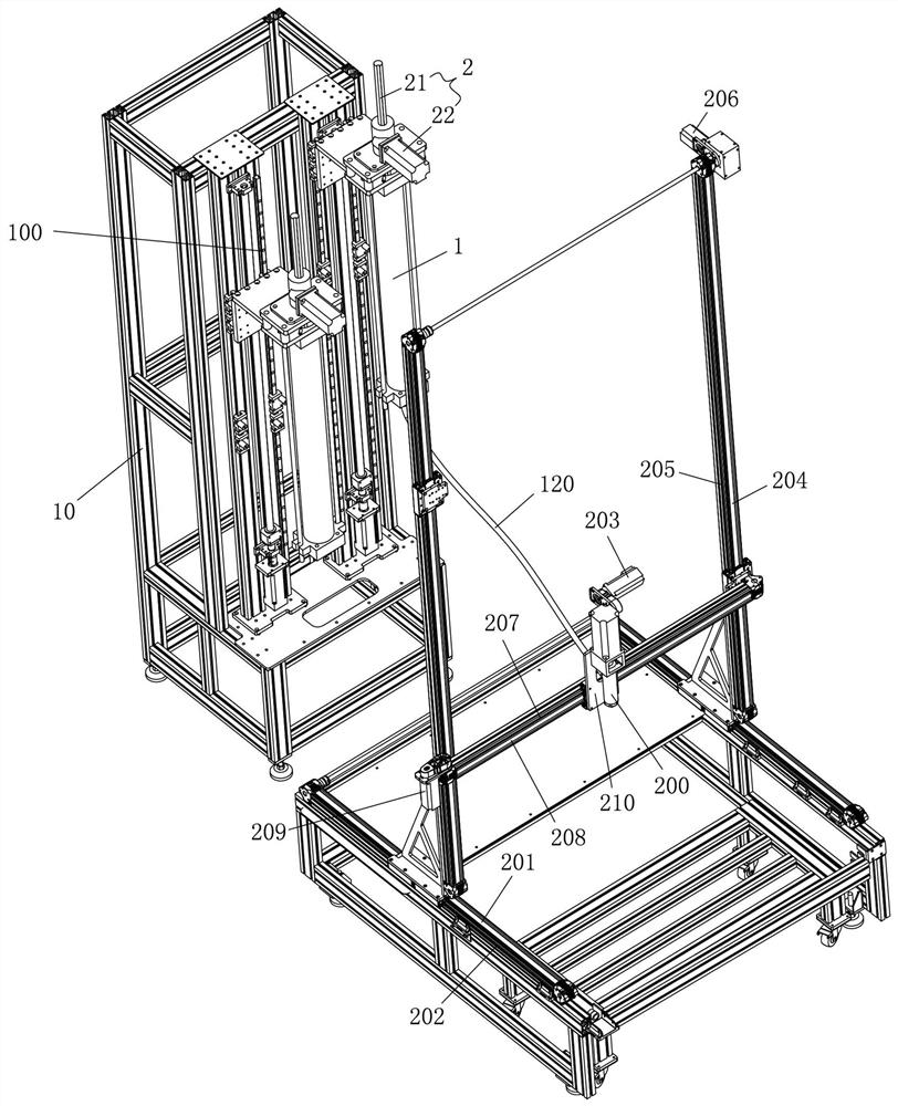
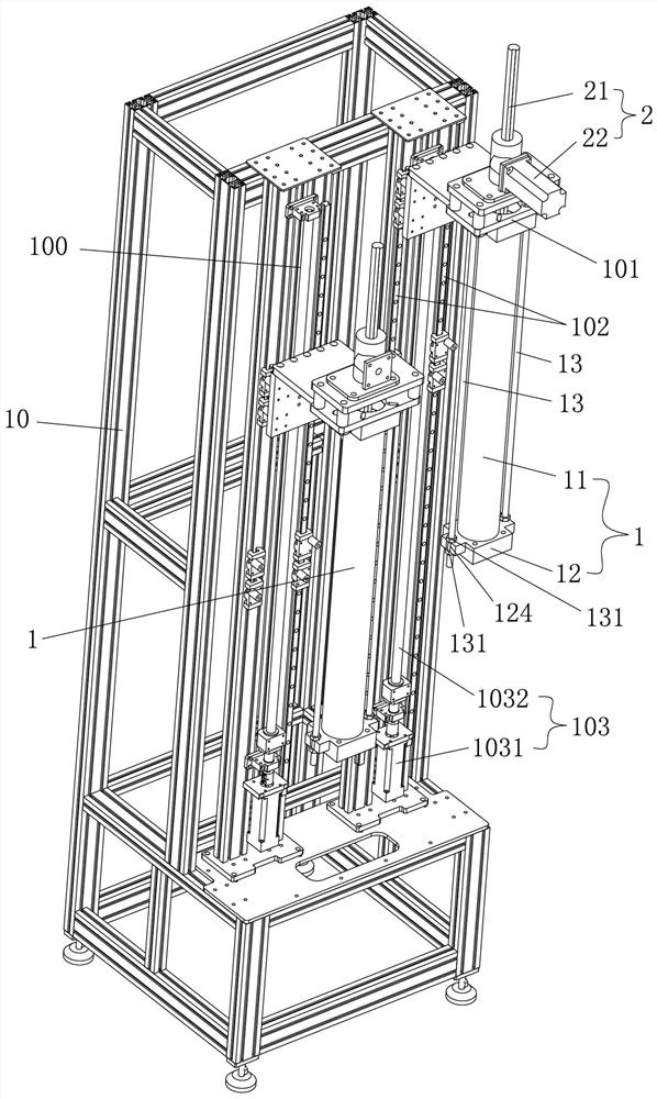
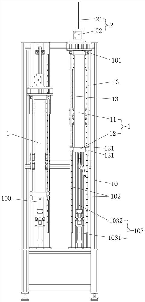
[0030] Such as Figure 1 to Figure 6 As shown, a 3D ceramic printer includes a mud feeding device 100 and a print head 200, the mud feeding device 100 includes a mud feeding frame 10, and a non-horizontally arranged columnar mud cylinder is installed on the mud feeding frame 10 1. The upper end of the mud cylinder 1 is open and the lower end is closed. A mud discharge through hole 121 is provided on the lower end of the mud cylinder 1. The mud cylinder 1 is correspondingly provided with a lifting rod mechanism 2. The lifting rod mechanism 2 includes a lifting rod mechanism 2. A rod 21 and a lifting drive mechanism 22, the lifting drive mechanism 22 is in transmission connection with the lifting rod 21, and is used to drive the lifting rod 21 to carry out lifting movement along the axial direction of the lifting rod ...


PUM


Abstract

The 3D ceramic printer comprises a mud conveying device and a printing head, the mud conveying device comprises a mud conveying rack, non-horizontal columnar mud barrels are installed on the mud conveying rack, the upper ends of the mud barrels are open, the lower ends of the mud barrels are closed, mud outlet through holes are formed in the lower ends of the mud barrels, and each mud barrel is correspondingly provided with a lifting rod mechanism; the lifting rod mechanism comprises a lifting rod and a lifting driving mechanism, the axis of the lifting rod is parallel to the axis of the mud barrel, and a piston is mounted at the lower end of the lifting rod, extends into the mud barrel from an opening in the upper end of the mud barrel and is attached to the mud barrel; and the mud outlet through hole is communicated with the printing head through a mud conveying pipe. According to the 3D ceramic printer, the piston presses the slurry downwards, power is provided for output of the slurry, meanwhile, the sealing effect is achieved, the slurry in the slurry barrel can be kept moist for a long time, and the problems that traditional slurry is prone to drying, and prepared slurry needs to be used immediately are effectively solved.

Description

technical field [0001] The invention relates to the field of ceramic production equipment, in particular to a 3D ceramic printer. Background technique [0002] 3D printing technology is a technology that uses bondable materials such as powdered metal or plastic to construct objects by layer-by-layer printing based on digital model files. Specifically, 3D printing equipment is used to allow the print head of the 3D printing equipment to run according to the program set by the digital model file, while extruding the bondable material, and stacking the object with the set shape layer by layer. 3D printing technology is limited by materials, and it is more used in the manufacture of some plastic models and plastic handicrafts. In the field of ceramic production, there are very few applications of 3D printing technology, and 3D ceramic printing is more in the conceptual stage and the practical stage. In some existing documents, although there are a small number of records of 3D...

Claims


Application Information

Patent Timeline
Patent Type & Authority Applications(China)
IPC IPC(8): B28B1/00B33Y30/00
Inventor 柯国镇曾绍锋徐高亮郑玉重
Owner QUANZHOU KUNTAI MACHINERY PRECISION MFG CO LTD
Learn More