Method and apparatus for forming composite part from multi-layer pre-preg composite charge

A prepreg and filling technology, applied to household components, household appliances, and other household appliances, can solve the problems of increasing manufacturing cycle time

Pending Publication Date: 2022-04-08
THE BOEING CO
View PDF0 Cites 0 Cited by
  • Summary
  • Abstract
  • Description
  • Claims
  • Application Information

AI Technical Summary

Problems solved by technology

Degassing typically increases manufacturing cycle time and

Method used


Image

  • Method and apparatus for forming composite part from multi-layer pre-preg composite charge
  • Method and apparatus for forming composite part from multi-layer pre-preg composite charge
  • Method and apparatus for forming composite part from multi-layer pre-preg composite charge

Examples


example 2

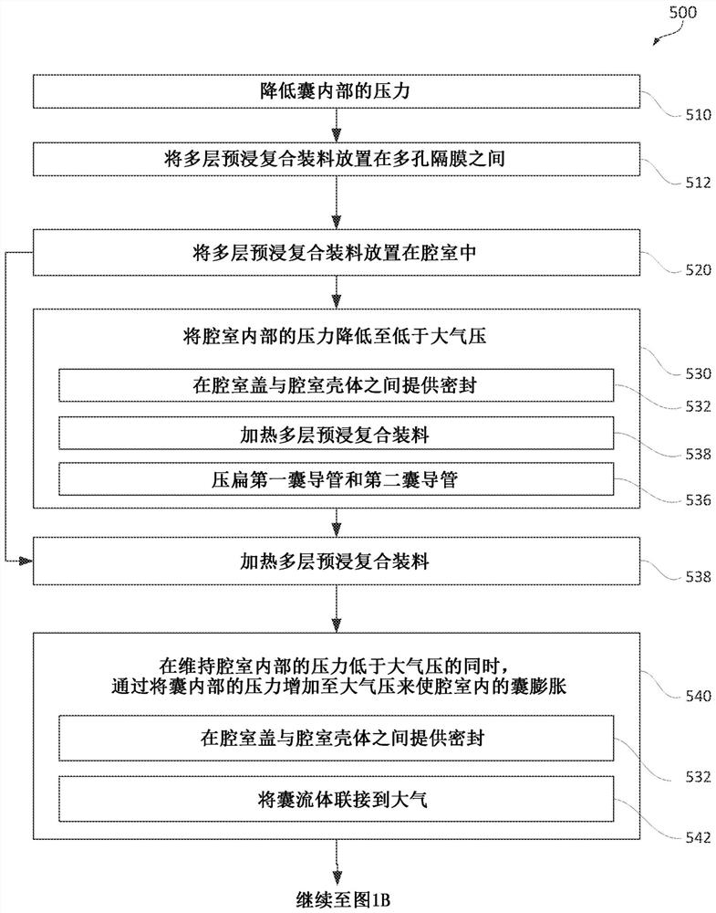
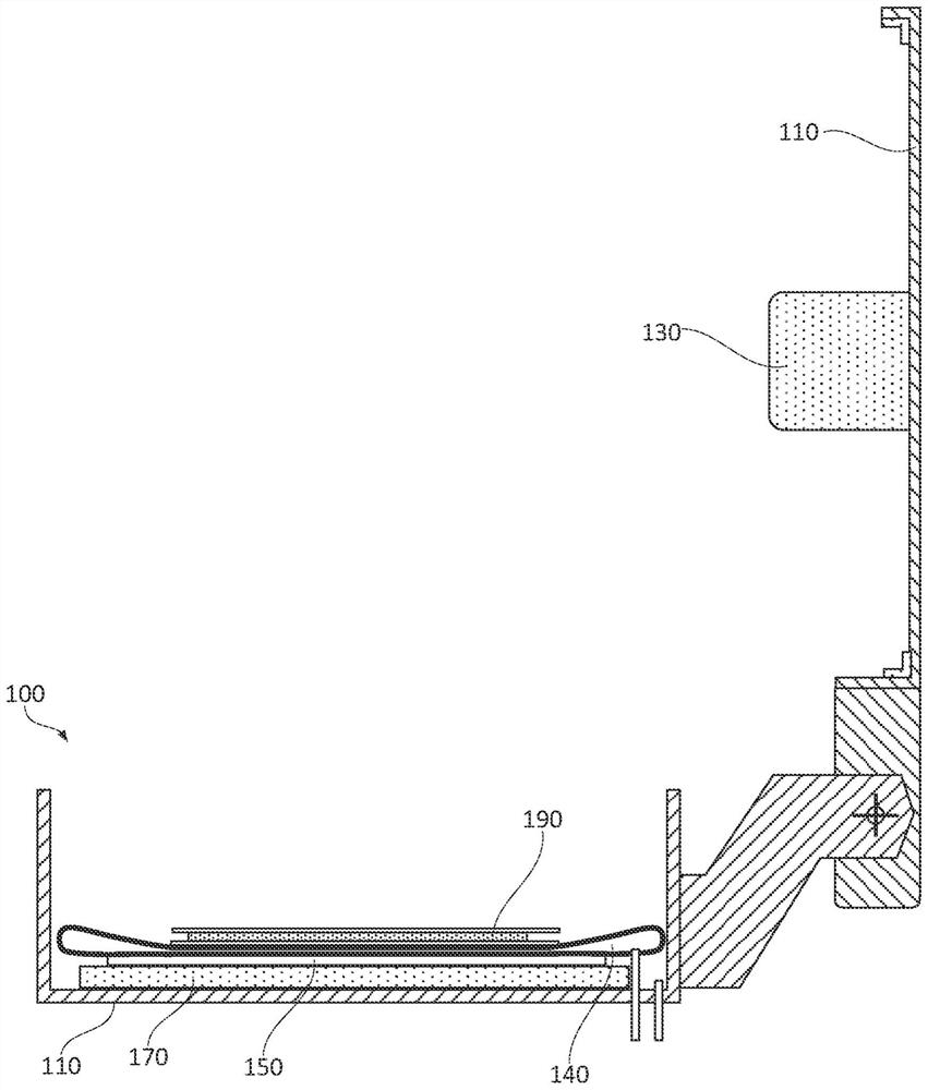
[0039] general reference Figure 1A with Figure 1B , especially for example Figure 3A to Figure 3B , for illustrative purposes only and not limitation, the following portion of this paragraph describes Example 2 of the subject matter disclosed herein. According to Example 2, which encompasses Example 1 above, during the step of reducing the pressure inside chamber 100 to below atmospheric pressure (block 510 ), multi-layer prepreg composite charge 190 is separated from forming tool 130 through gap 134 .

[0040] Gap 134 ensures that the portion of multilayer prepreg composite charge 190 facing forming tool 130 remains exposed and available for degassing (or more specifically, initial degassing prior to compressing multilayer prepreg composite charge 190 ). Once the forming tool 130 is in contact with the multi-layer prepreg composite charge 190 and the multi-layer prepreg composite charge 190 is compressed between the bladder 140 and the forming tool 130, the degassing path...

example 3

[0042] general reference Figure 1A with Figure 1B , especially for example figure 2 , Figure 3A with Figure 3B , for illustrative purposes only and not limitation, the following portion of this paragraph describes Example 3 of the subject matter disclosed herein. According to Example 3 covering Example 2 above, the chamber 100 includes a chamber case 110 and a chamber cover 120 coupled to the chamber case 110 and pivotable relative to the chamber case 110 . The step of reducing the pressure inside the chamber 100 to below atmospheric pressure (block 530) and reducing the pressure inside the chamber 100 by increasing the pressure inside the bladder 140 to atmospheric pressure while maintaining the pressure inside the chamber 100 below atmospheric pressure. The steps of inflating the bladder 140 (block 550 ) each include (block 532 ) providing a seal between the chamber cover 120 and the chamber housing 110 . The forming tool 130 is attached to and supported by the cham...

example 5

[0047] general reference Figure 1A with Figure 1B , especially for example Figure 3A with Figure 3B, for illustrative purposes only and not limitation, the following portion of this paragraph describes Example 5 of the subject matter disclosed herein. According to Example 5, which encompasses Example 4 above, heating the multi-layer prepreg composite charge 190 prior to inflating the bladder 140 within the chamber 100 (block 538) reduces the pressure inside the chamber 100 to below atmospheric pressure ( Block 530) is executed thereafter.

[0048] Heating the multi-layer prepreg composite charge 190 prior to inflating the bladder 140 within the chamber 100 facilitates degassing the multi-layer prepreg composite charge 190 . Such as Figure 3A with Figure 3B As shown, the forming tool 130 is not in contact with the multi-layer prepreg composite charge 190 at this stage, and the entire surface of the multi-layer prepreg composite charge 190 is exposed or covered by per...


PUM


Abstract

A method and apparatus for forming a composite part from a multi-layer pre-preg composite charge. A method (500) of forming a composite part (195) from a multi-layer prepreg composite charge (190) includes reducing a pressure inside a bladder (140) located in a chamber (100) at atmospheric pressure to below atmospheric pressure. The method (500) further includes placing the multi-layer prepreg composite charge (190) having the first shape in the chamber (100) and reducing the pressure inside the chamber (100) to below atmospheric pressure. The method (500) further includes expanding the bladder (140) within the chamber (100) by increasing the pressure inside the bladder (140) to atmospheric pressure while maintaining the pressure inside the chamber (100) below atmospheric pressure such that the multi-ply prepreg composite charge (190) is compressed between the bladder (140) and the forming tool (130) located inside the chamber (100), and the multi-ply prepreg composite charge (190) is configured by the forming tool (130) in a second shape different from the first shape. The method (500) also includes curing the multi-layer prepreg composite charge (190) having the second shape.

Description

technical field [0001] This invention relates to methods and apparatus for forming composite parts from multilayer prepreg composite charges. Background technique [0002] Composite materials are becoming increasingly popular for making aircraft components and other lightweight structures. Composite materials have excellent strength and stiffness properties and are lightweight compared to, for example, metals. However, composite structures are still relatively expensive to manufacture, eg compared to metallic structures. Manufacturing costs are especially significant for large composite structures and composite structures with complex geometries. The main factors contributing to these high manufacturing costs are equipment complexity and processing time. For example, processing of composite materials often involves degassing, ie, extraction of moisture, volatiles and / or gases trapped in these materials. Degassing typically increases manufacturing cycle time and requires ...

Claims


Application Information

Patent Timeline
IPC IPC(8): B29C70/44B29L31/30
CPCB29C70/342B29C70/56B29C70/541B29C2043/3649B29C70/30B29C70/446B29C33/50B29C43/12B29C2043/561B29C43/56B29C43/52B29C70/44B29C70/54B29L2031/3076
Inventor A·E·莫丁D·马丁R·E·赫斯E·C·安德森C·J·汉德莱素R·A·普劳泽M·C·哈格罗夫三世J·H·瑞吉斯特
Owner THE BOEING CO
Why Eureka
Try Eureka