A casing slip supporting device and its use method
A slip matching and casing technology, which is applied in unloading devices, packaging, etc., can solve the problems of casing slips being easy to fall, unfavorable handling, and tripping drill floor workers, so as to improve the stability of use and reduce the The difficulty of bundling and the effect of easy transfer and handling
- Summary
- Abstract
- Description
- Claims
- Application Information
AI Technical Summary
Problems solved by technology
Method used
Image
Examples
Embodiment 1
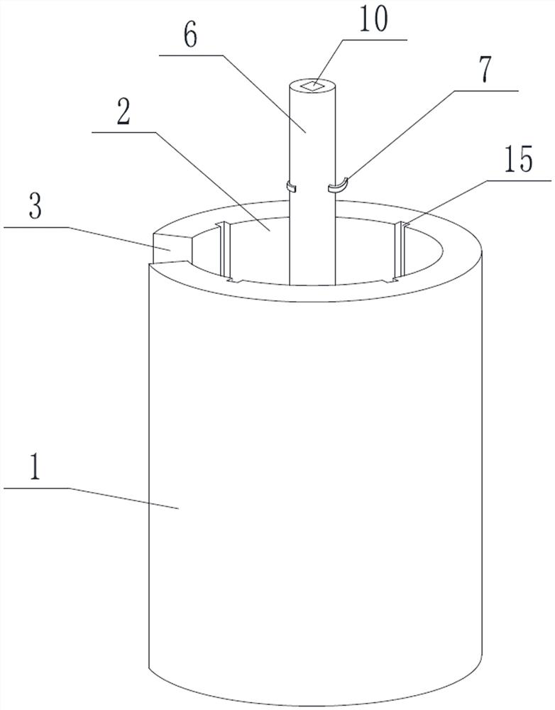
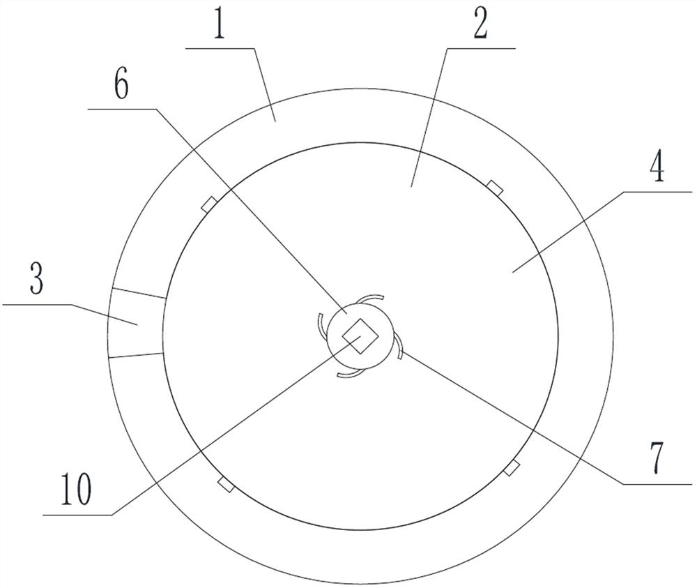
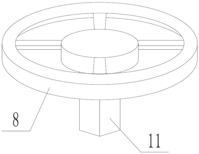
[0046] Such as Figure 1 to Figure 3 The casing slip matching device shown includes a box body 1 and an annular groove 2 opened on the top surface of the box body 1. The side of the annular groove 2 has a first gap 3 communicating with the outside of the box body 1. The top of the first notch 3 is open, and also includes a lifting platform 4 located inside the box body 1, a driving device 5 for driving the lifting platform 4 up and down, and a rotating shaft 6 that is rotatably matched with the lifting platform 4. The rotating shaft 6 protrudes from the top of the annular groove 2 to the outside of the box body 1, and also includes several circular hooks 7 uniformly distributed on the outer wall of the rotating shaft 6 in the same direction of rotation, and the hooks 7 are located outside the box body 1; it also includes a detachable connection The handle 8 at the top of the rotating shaft 6. A square hole 10 is provided at the top of the rotating shaft 6, and a square insert...
Embodiment 2
[0060] A casing slip supporting device, on the basis of Embodiment 1, also includes a sheath 12 for placing in the annular groove 2, such as Figure 4 and Figure 5 As shown, the shape of the sheath 12 matches the groove type of the annular groove 2; the top surface of the sheath 12 is open and the bottom surface is closed, and the bottom surface of the sheath 12 is provided with an anti-collision hole 13, and the anti-collision hole 13 is used to avoid the The sleeve 12 interferes with the rotating shaft 6 and the crotch 7 when entering and leaving the annular groove 2 .
[0061] The sheath 12 is annular, and the outer diameter of the sheath 12 is equal to the inner diameter of the annular groove 2 , and the side wall of the sheath 12 is provided with a second notch 14 equal in width to the first notch 3 .
[0062] The inner wall of the annular groove 2 is provided with a plurality of longitudinally distributed limiting grooves 15, the top of the limiting grooves 15 is conne...
Embodiment 3
[0069] A casing slip supporting device, on the basis of any of the above-mentioned embodiments, such as Figure 8 As shown, the bottom end of the rotating shaft 6 is rotatably connected to the bottom of the annular groove 2, the outer wall of the rotating shaft 6 is movably sleeved with a sliding sleeve 17, and a through hole is opened on the lifting table 4, and the sliding sleeve 17 is fixedly connected to the through hole. On the inner wall of the hole, the rotating shaft 6 and the lifting platform 4 realize rotational cooperation through a sliding sleeve 17 .
[0070] The driving device 5 in this embodiment cannot interfere with the rotating shaft 6, as Figure 8 As shown, the driving device 5 is composed of several circularly distributed elevators, and all the elevators need to be linked synchronously.
[0071] It should be noted that the attached Figure 8 The cross-section passes through the first gap 3 .
PUM
 Abstract
Description
Claims
Application Information
 - R&D
- Intellectual Property
- Life Sciences
- Materials
- Tech Scout
- Unparalleled Data Quality
- Higher Quality Content
- 60% Fewer Hallucinations
Browse by: Latest US Patents, China's latest patents, Technical Efficacy Thesaurus, Application Domain, Technology Topic, Popular Technical Reports.
© 2025 PatSnap. All rights reserved.Legal|Privacy policy|Modern Slavery Act Transparency Statement|Sitemap|About US| Contact US: help@patsnap.com


