Fixture for correcting drilling path of drill bit

A fixture and path technology, used in drilling/drilling equipment, manufacturing tools, components of boring machines/drilling machines, etc., can solve the problem of inability to guarantee the processing size, and achieve the effect of stable path

Active Publication Date: 2022-04-12
HUBEI TRI RING FORGING
View PDF7 Cites 0 Cited by
  • Summary
  • Abstract
  • Description
  • Claims
  • Application Information

AI Technical Summary

Problems solved by technology

[0005]According to the problems existing in the prior art, the present invention provides a drilling path correction jig, especially for processing the diaphragm flange 103 In the case that only one side of the drill bit is under force and the processing size cannot be guaranteed, this correction fixture is used to ensure the stability of the processing size

Method used


Image

  • Fixture for correcting drilling path of drill bit
  • Fixture for correcting drilling path of drill bit
  • Fixture for correcting drilling path of drill bit

Examples


Embodiment Construction

[0028] The principles and features of the present invention are described below in conjunction with the accompanying drawings, and the examples given are only used to explain the present invention, and are not intended to limit the scope of the present invention.

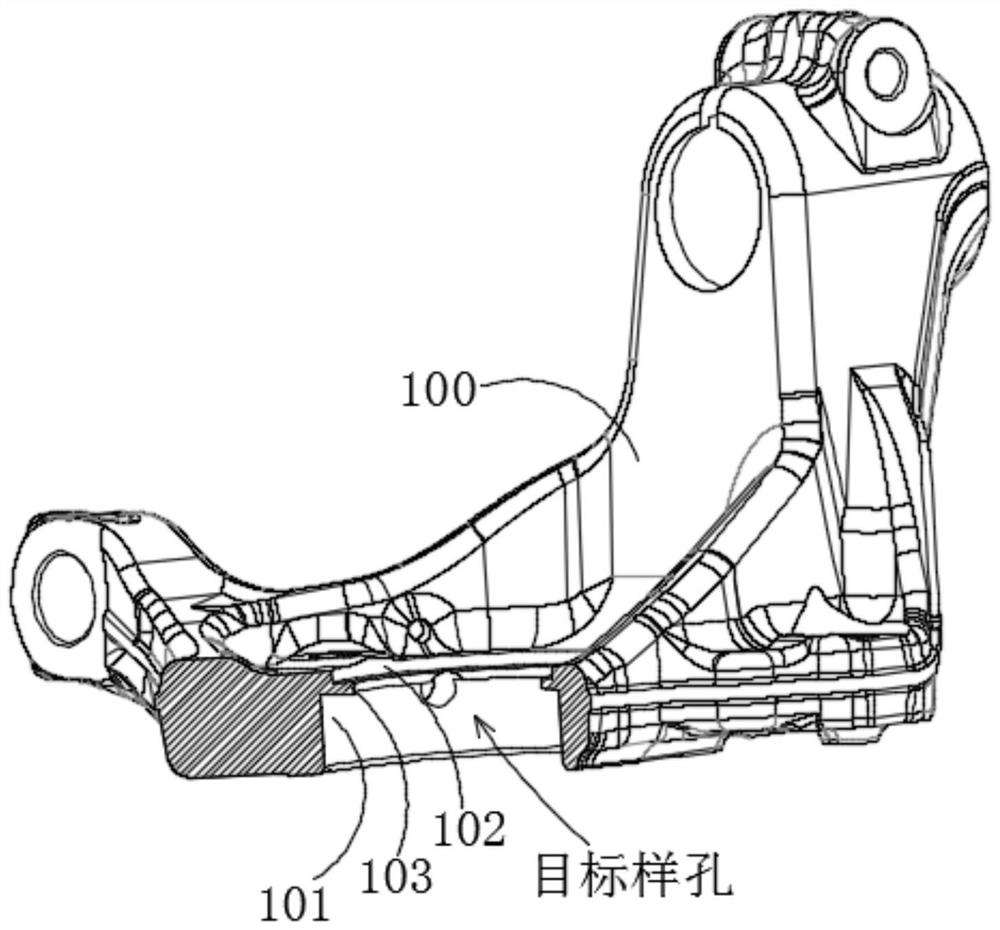
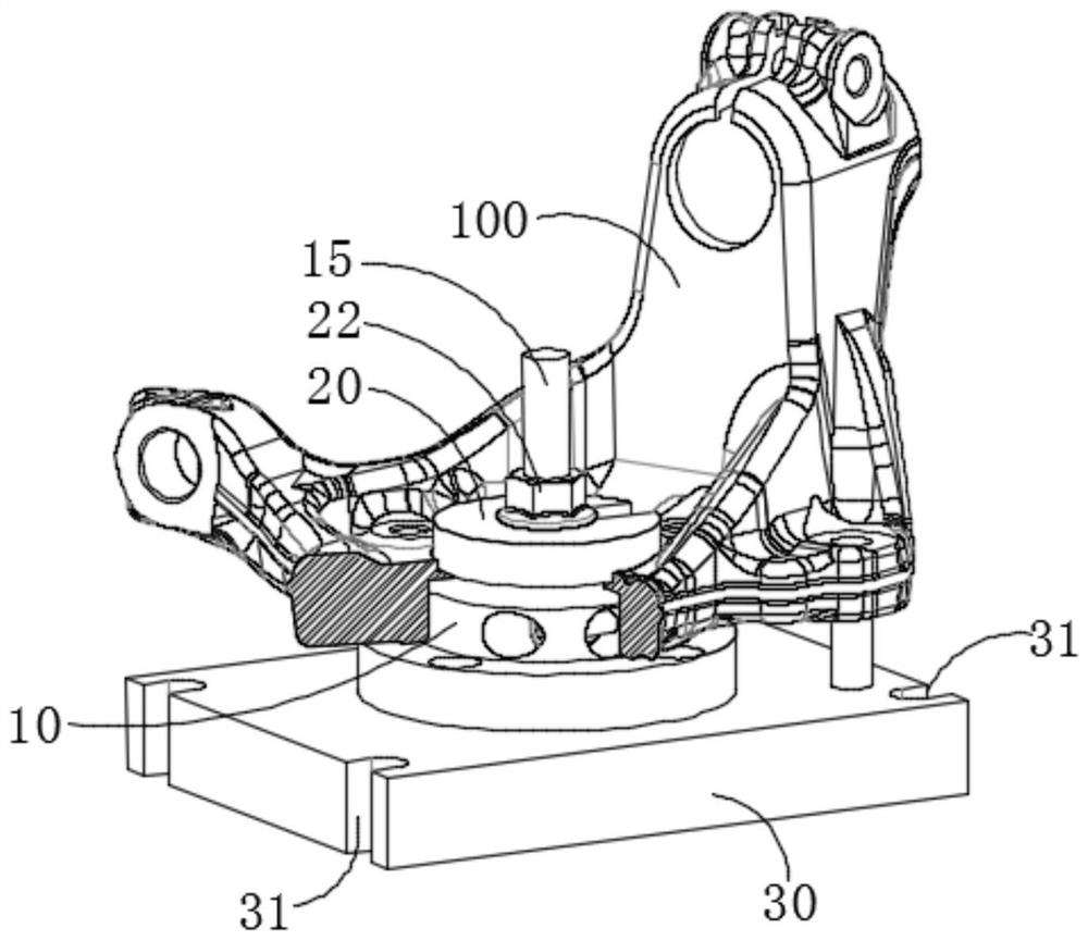
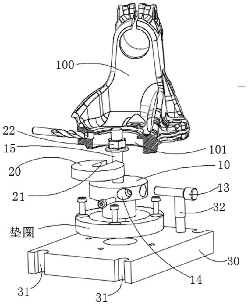
[0029] This embodiment provides a drill bit drilling path correction jig, the correction jig is mounted on the steering knuckle, when the steering knuckle is drilled, the needle roller 13 in the correction jig is used to pair the tool (that is, the alloy drill bit) Provide support to prevent the unilateral force on the drill bit during cutting and drilling, and the downward deviation of the drill bit will cause the deviation of the processing size of the steering knuckle.

[0030] In this program, see Figure 2-Figure 6 , the provided drill drilling path correction jig needs to be fixed with the steering knuckle 100 to facilitate the drilling operation of the alloy drill on the steering knuckle; specifically, the co...


PUM


Abstract

The invention discloses a drill bit drilling path correcting clamp, and relates to a drilling machining tool, the correcting clamp is fixed with a steering knuckle to facilitate the drilling operation of an alloy drill bit on the steering knuckle, the correcting clamp comprises a positioning mandrel, and the positioning mandrel is matched with a first shaft hole part of the steering knuckle; a receding groove is formed in the upper end face of the positioning mandrel in the radial direction. The through hole is formed under the clearance groove and extends in the length direction of the clearance groove; the top of the through hole is partially overlapped with the bottom of the clearance groove; the roller pin is arranged in the through hole in a filling manner; at least part of the roller pin is located in the clearance groove; the roller pin is used for providing support for the alloy drill bit when the alloy drill bit performs punching operation on the steering knuckle; according to the scheme, the rolling needle is used for supporting the alloy drill bit, the situation that the drill bit deviates and cutter back-off occurs in the machining process is avoided, and the cutter (namely the alloy drill bit) cannot deviate in the machining process by means of supporting limitation of the rolling needle.

Description

technical field [0001] The invention relates to a drilling tool, in particular to a jig for correcting the drilling path of a drill bit. Background technique [0002] Steering Knuckle, also known as "horn", is one of the important parts in the steering axle of a car, which can make the car run stably and transmit the driving direction sensitively. The function of the steering knuckle is to transmit and bear the front load of the car, support and drive the front wheel to rotate around the kingpin to turn the car. [0003] The shaft hole in the steering knuckle is an important connection part, and it is a common operation method to drill holes in the shaft hole to facilitate subsequent installation; for the convenience of introduction, here is a further detailed introduction to the shaft hole of the steering knuckle , that is, the shaft hole includes a first shaft hole portion 101 and a second shaft hole portion 102, wherein there is a separator flange 103 between the first s...

Claims


Application Information

Patent Timeline
Patent Type & Authority Applications(China)
IPC IPC(8): B23B49/00
Inventor 张运军邴涵王战兵徐记洪许新亮柳伟夏少仙杨超杨林杨军伟张剑
Owner HUBEI TRI RING FORGING
Why Eureka
Try Eureka