Reciprocating motion type flying shear mechanism

A technology of reciprocating movement and flying shear, which is applied in the direction of shearing devices, shearing machine equipment, shearing machine accessories, etc., can solve the problems of inconvenient reciprocating synchronous derivation, inconvenient periodic drive regulation, and inability to form continuous coordination. Achieve the effect of facilitating reciprocating synchronous derivation, helping cutting operation production, and facilitating production settings

Inactive Publication Date: 2022-04-12
龚儒丰
View PDF1 Cites 0 Cited by
  • Summary
  • Abstract
  • Description
  • Claims
  • Application Information

AI Technical Summary

Problems solved by technology

[0004] There is a phenomenon that it is not convenient for reciprocating synchronous derivation, it is not conducive to continuous production and processing, and it will cause certain inconvenience. There is also the phenomenon that the inner end track device, the drive connection device, and the conduction device cannot form a continuous fit, which needs to be improved

Method used


Image

  • Reciprocating motion type flying shear mechanism
  • Reciprocating motion type flying shear mechanism
  • Reciprocating motion type flying shear mechanism

Examples


Embodiment Construction

[0028] The following will clearly and completely describe the technical solutions in the embodiments of the present invention with reference to the accompanying drawings in the embodiments of the present invention. Obviously, the described embodiments are only some, not all, embodiments of the present invention. Based on the embodiments of the present invention, all other embodiments obtained by persons of ordinary skill in the art without making creative efforts belong to the protection scope of the present invention.

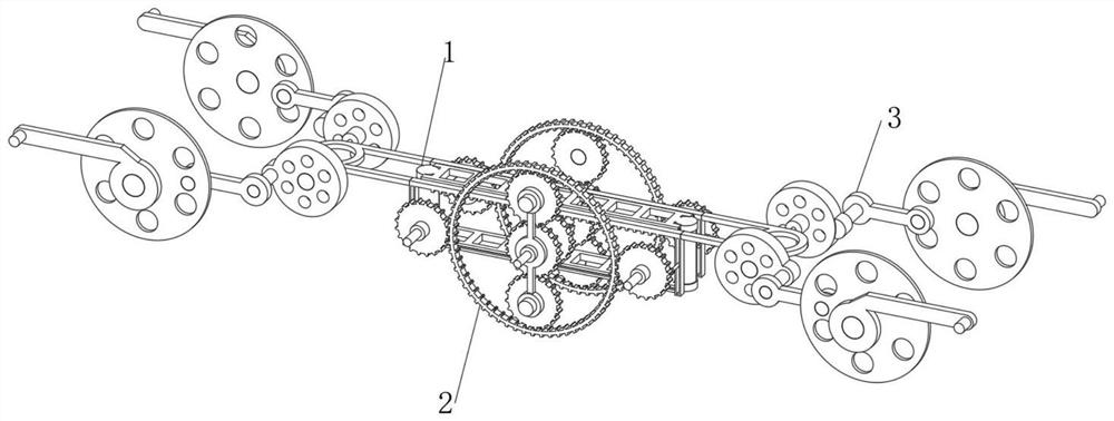
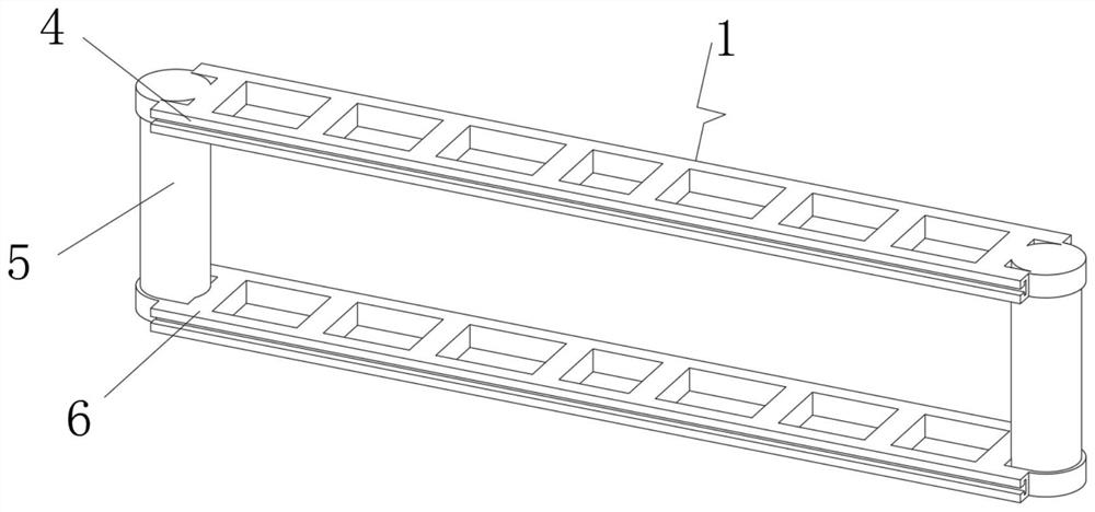
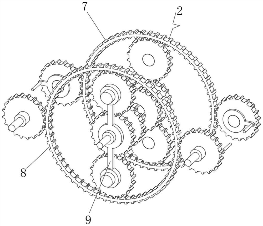
[0029] see Figure 1-7 , the present invention provides a technical solution: a reciprocating flying shear mechanism, including a track device 1, a conduction device 3 is slidably connected to the side end of the track device 1, and a driving connection is engaged and connected to the lower end of the conduction device 3 Device 2, by installing the track device 1 and the drive connection device 2, the track device 1 is set through the structure of the inner en...


PUM


Abstract

The reciprocating type flying shear mechanism comprises a rail device, a conduction device is slidably connected to the side end position of the rail device, a driving connection device is connected to the lower end position of the conduction device in a meshed mode, and the rail device comprises a first rail frame, a connection frame and a second rail frame; the second rail frame is erected at the bottom of the inner end of the rail device, the upper end of the second rail frame is fixedly connected with the connecting frame, the upper end of the connecting frame is fixedly connected with the first rail frame, and the driving connecting device comprises a first driving structure, a second driving structure and a connecting rod frame. The second driving structure is arranged at the front part of the inner end of the driving connecting device, and the rear end of the second driving structure is synchronously connected with the first driving structure. According to the reciprocating flying shear mechanism, the purpose of inner end driving connection is achieved through the arrangement of the driving connection device.

Description

technical field [0001] The invention relates to the technical field of mechanical equipment, in particular to a reciprocating flying shear mechanism. Background technique [0002] According to the Chinese Patent No. CN201910876572.9, the present invention discloses a reciprocating flying shear mechanism. The shearing mechanism includes from top to bottom: a cylinder, a column, a ram and a slide rail. The cylinder is fixed to the upper end of the column. The ram is fixedly connected to the lower end of the column; the shaft body at the bottom of the cylinder is fixedly connected with a moving beam, the right end of the moving beam is fixedly connected with an upper knife, and the right end of the ram is fixedly connected with a lower knife corresponding to the upper knife, and the lower knife is fixedly connected with the upper knife. The upper end is attached to the lower surface of the workpiece; the ram is horizontally slidably set on the slide rail, and the two ends of th...

Claims


Application Information

Patent Timeline
Patent Type & Authority Applications(China)
IPC IPC(8): B23D25/02B23D33/00
Inventor 龚儒丰
Owner 龚儒丰
Why Eureka
Try Eureka