Clamping mechanism

A technology of clamping mechanism and guiding structure, which is applied in the direction of workpiece clamping devices and manufacturing tools, can solve the problems of single structural design principle and inability to adjust the clamping size adaptively, so as to prevent bumps and scratches, novel structural design, The effect of improving performance

Active Publication Date: 2022-04-12
DONGFENG OFF ROAD VEHICLE CO LTD
View PDF4 Cites 2 Cited by
  • Summary
  • Abstract
  • Description
  • Claims
  • Application Information

AI Technical Summary

Problems solved by technology

Most of the existing clamping mechanisms directly and symmetrically drive the centripetal movement of each jaw through the driving device to realize the clamping of the clamped part. The structural design principle is relatively simple, and the size of the clamped part is a set value, which cannot be carried out Adaptive adjustment of clamping size

Method used


Image

  • Clamping mechanism
  • Clamping mechanism
  • Clamping mechanism

Examples


Embodiment 1

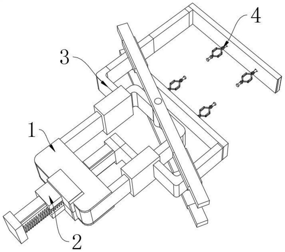
[0027] like Figure 1-5 A clamping mechanism of the present invention is shown, including a two-way guiding structure 1, an active clamping structure 2 and a driven clamping structure 3,

[0028] The two-way guide structure 1 includes a fixed base 17, a first slide rail 18 and a second slide rail 19 arranged in parallel on one side of the fixed base 17, and a second slide rail 19 is arranged between the first slide rail 18 and the second slide rail 19. Center pin 20, the top and the bottom of center pin 20 are all rotatably connected with offset linkage rod 21, and the inside of one end of two offset linkage levers 21 is all slidingly provided with active connecting block 22, and the inside of the other end is all slidingly provided with driven connection block 23,

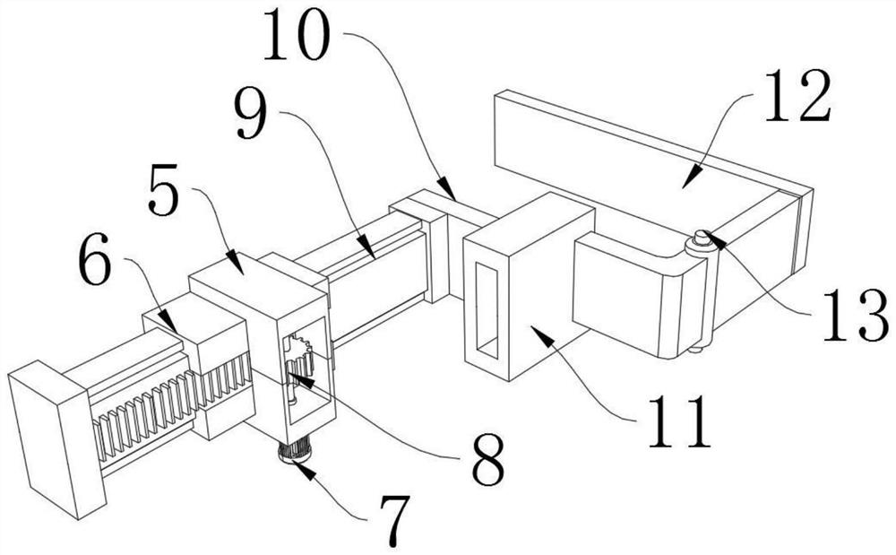
[0029] The active clamping structure 2 includes a driving device and a first sliding guide block 11, the first sliding guiding block 11 is slidably connected with the second sliding rail 19, and the driving devic...


PUM


Abstract

The clamping mechanism comprises a two-way guide structure, a driving clamping structure and a driven clamping structure, the two-way guide structure comprises a fixedly-installed base, a first sliding rail and a second sliding rail, the first sliding rail and the second sliding rail are arranged on one side of the fixedly-installed base in parallel in a spaced mode, and a center pin column is arranged between the first sliding rail and the second sliding rail; the center pin column is rotationally connected with an offset linkage rod, the driving clamping structure comprises a driving device and a first sliding guide block, the first sliding guide block is in sliding connection with the second sliding rail, the driven clamping structure comprises a second sliding guide block, and the second sliding guide block is in sliding connection with the first sliding rail. The first sliding guide block is driven by the driving device to slide on the second sliding rail, and the second sliding guide block is driven by the offset linkage rod to slide reversely on the first sliding rail, so that opposite movement of the driving clamping push rod and the driven clamping push rod is realized and is stopped until a clamped part is clamped, self-adaptive clamping is realized, the two clamping jaws are mutually linked, and the clamping efficiency is improved. The clamping force is the same, and reliable and stable clamping is achieved.

Description

technical field [0001] The invention relates to the technical field of mechanical clamping, in particular to a clamping mechanism. Background technique [0002] With the promotion of mechanical automation, more and more manual work is replaced by machinery. Among them, the manipulator and mechanical clamping mechanism play an important role to realize the clamping, handling, and circulation of workpieces, thus forming an automated production line. Most of the existing clamping mechanisms directly and symmetrically drive the centripetal movement of each jaw through the driving device to realize the clamping of the clamped part. The structural design principle is relatively simple, and the size of the clamped part is a set value, which cannot be carried out Adaptive adjustment of clamping size. Contents of the invention [0003] The technical problem to be solved by the present invention is to provide a clamping mechanism with a novel structural design, stable and reliable ...

Claims


Application Information

Patent Timeline
Patent Type & Authority Applications(China)
IPC IPC(8): B25B11/00
CPCY02P70/50
Inventor 王之甫
Owner DONGFENG OFF ROAD VEHICLE CO LTD
Why Eureka
Try Eureka