Air floatation motion platform
A motion platform and air flotation technology, applied in the direction of workbench, manufacturing tools, etc., can solve the problems of air flotation guide rail deformation, motion jamming, air film thickness change, etc., and achieve the effect of reducing guide rail deformation
Pending Publication Date: 2022-04-12
ZHONGSHAN AISCENT TECH
0 Cites 0 Cited by
AI-Extracted Technical Summary
Problems solved by technology
With the release of assembly stress, temperature changes, and changes in horizontal conditions, the air-floating guide rail will be deformed and twisted to ch...
Method used
It can be understood that gas enters from an air inlet 312, which can make the introduction of gas convenient, while gas can be blown out from multiple gas outlets 313 to make gas outlet more smoothly, and multiple gas outlets 313 are in the first package 310 Air outlet at different positions can also make the air film formed before the first package 310 and the first guide rail 200 more uniform and stable.
It can be understood that the second airway inlet 511 and the second airway outlet 512 cooperate to form a high rigidity structure with an air film between the second movement assembly 500 and the second guide rail 400, and the second movement The air film between the assembly 500 and the second guide rail 400 can ensure the stability of the motion assembly formed by the combination of the first motion assembly 300 and the second motion assembly 500 .
It can be understood that the second recessed portion is provided for setting the linear motor to make the structure of the air-floating motion platform more compact. to drive.
It should be noted that the first recess 410 is provided on the first guide rail 200 and/or the second guide rail 400 to accommodate the linear motor for driving the first motion assembly 300 or the second motion assembly 500, and the linear motor Being arranged in the first reces...
Abstract
The invention discloses an air floatation motion platform, which comprises a base, the first guide rail is arranged on the base; the first movement assembly is arranged on the first guide rail and can move relative to the first guide rail, the first movement assembly comprises a first wrapping part and two second wrapping parts, the first wrapping part is connected with the two second wrapping parts and located above the first guide rail, and the two second wrapping parts are located on the two sides of the first guide rail correspondingly; the second wrapping piece is in clearance fit with the first guide rail; the first air channel is arranged on the first wrapping piece and used for feeding air so that a first air film can be formed between the first guide rail and the first wrapping piece. Through the structure, the effect of reducing the influence of deformation and distortion of the guide rail on the thickness of an air film can be achieved.
Application Domain
Work benches
Technology Topic
Structural engineeringMechanical engineering +1
Image
Examples
- Experimental program(1)
Example Embodiment
[0023] Embodiments of the present invention will be described in detail below, and examples of the embodiments are illustrated in the drawings, in which the same or similar reference numerals represent the same or similar elements or elements having the same or similar functions. The following is exemplary, and is intended to be illustrative of the invention, not to be construed as limiting the invention.
[0024] In the description of the present invention, it is to be understood that the orientation or positional relationship of the orientation, such as upper, lower, prior,,, left, right, etc., based on the orientation or positional relationship shown in the drawings, is only In order to facilitate the description of the invention and simplified description, rather than indicating or implying that the device or element must have a specific orientation, constructing and operating in a particular orientation, and thus is not to be construed as limiting the invention.
[0025] In the description of the present invention, several meanings are one or more, and multiple meanings are more than two, greater than, less than, more than, etc. If there is a first, the second is only the purpose of distinguishing the technical feature, and cannot be understood as an indication or implies a relative importance or implicitly indicated the number of technical features indicated or implicitly indicated. relation.
[0026] In the description of the present invention, unless otherwise expressly defined, set, mounting, connection, etc.
[0027] It should be noted that the features of the present application and the features in the embodiments in the present application can be combined with each other in the case of an unable conflict. The present invention will be described in detail below with reference to the accompanying drawings.
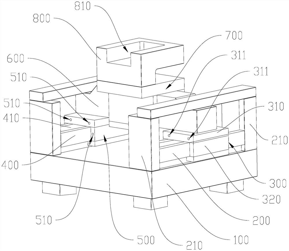
[0028] Refer figure 1 and Figure 4 In some embodiments of the present invention, the air floating motion platform includes: the base 100, the first guide rail 200 of the base 100; the first moving assembly 300, is provided in the first rail 200 and can be relative to the first rail 200 Move, the first motion assembly 300 includes a first wrap piece 310 and two second wrap pieces 320, and the first package 310 is connected to the two second wrap portions 320, and the first wrap 310 is located above the first rail 200. The two second wrap pieces 320 are respectively located on both sides of the first rail 200, and the second wrap piece 320 cooperates with the first guide rail 200; the first airway 311 is disposed at the first parcel 310, the first airway 311, respectively. Used in intake air to form a first gas film between the first rail 200 and the first wrap 310.
[0029] It should be noted that the base 100 is the marble base 100, the marble base 100 is long, which is higher than the hardness of the cast iron, and will not be influenced by the ambient temperature and humidity, so that the entire gas float moving platform can be made more stable.
[0030] It should be noted that in some embodiments of the present use, the first rail 200 is directly protruding from the marble base 100 body, and the guide rail of the marble material has the advantages of marble, and the stability is higher.
[0031] It will be appreciated that the first rail 200 can also be made of ceramics, cast iron, etc., mounted to the base 100.
[0032] In addition, the first airway 311 is provided in the first wrap 310, and the first airway 311 is used for intake to form a first gas film between the first rail 200 and the first wrap 310. The gas film enables the first wrap piece 310 of the first moving assembly 300 in the first rail 200, and the second wrap 320 connected to the first wrap 310 and the first rail 200 gaps, so that The entire first moving assembly 300 is not in contact with the first rail 200.
[0033] It will be appreciated that the gas float moving platform provided by the present invention only, the air floating motion platform provided by the present invention, and the gas planes of the first wrap 310 and the guide rail are retained. On the side of the guide rail 200, the gap between the second wrapper member 320 and the first motor assembly 300 and the first rail 200 can also greatly reduce the degree of sensitivity of the gas film thickness to the guide rail, distortion, so that gas The film thickness is more stable, which in turn makes the entire gas floating platform more stable.
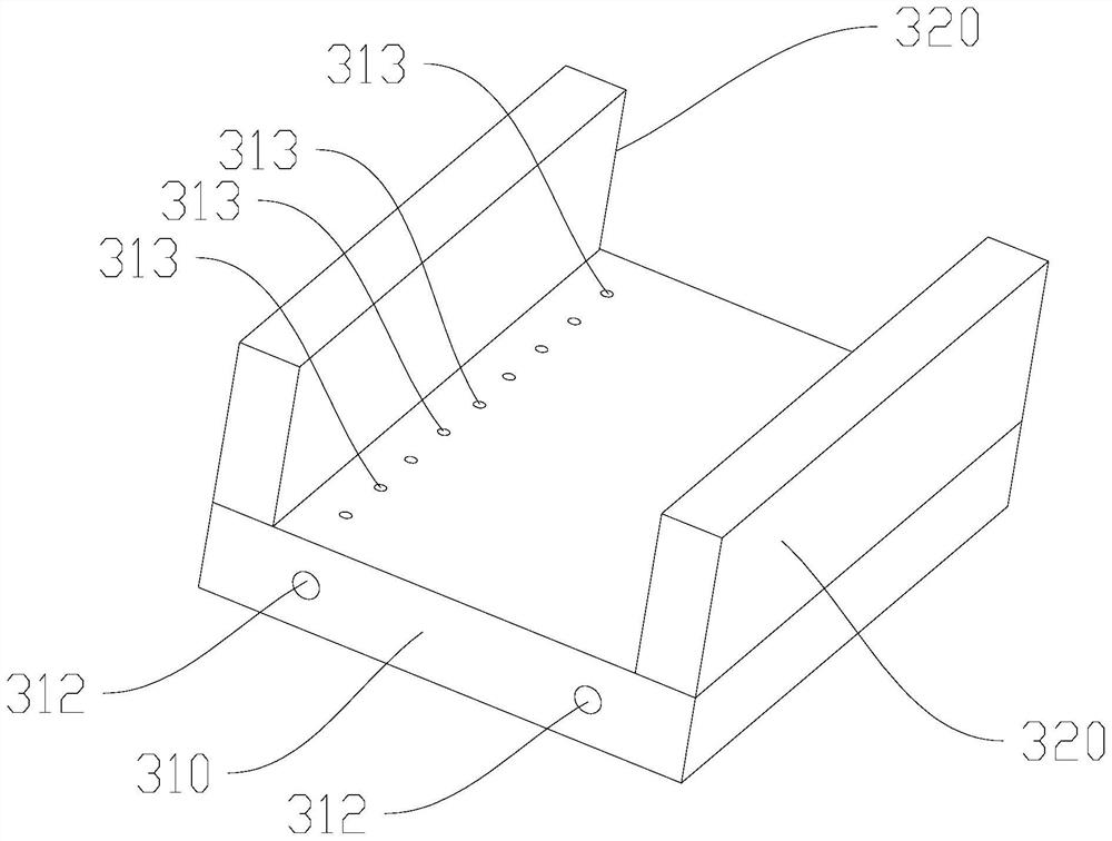
[0034] Refer figure 2 In some embodiments of the invention, the first airway 311 includes air intake port 312 and a plurality of air outlets 313, and a plurality of air port 313 communicate with the intake port 312, and a plurality of air port 313 is set to the first The surface of the first package 310 corresponding to the guide rail 200.
[0035] Specifically, the gas delivery air port 312 is blown from the outside to the first wrap piece 310, from each of the air port 313 in the surface of the first wrap 310 corresponding to the first guide rail 200, from the outer air port 312. The gas blown out of the air inlet 313 forms a micron-stage gas film between the first rail 200 and the first wrap piece 310.
[0036] It will be appreciated that the gas can enter from one air interface 312, which can introduce the gas into the gas, and the gas blows from the plurality of outlet port 313 so that the gas extra gas is smoother, and the plurality of air port 313 is in different positions of the first wrap 310. The ventilation can also make the first wrapper 310 and the first guide rail 200 formed by the gas film formed more uniform and stable.
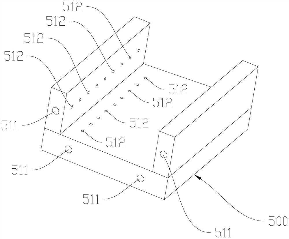
[0037] Refer figure 1 , image 3 andFigure 4 In some embodiments of the invention, the air floating motion platform further includes a second rail 400, a second moving assembly 500, and a second airway 510, and the second rail 400 is located in the base 100 and is set to the first rail 200. The second moving assembly 500 is provided in the second rail 400 and can be moved relative to the second rail 400, and the second moving assembly 500 is connected to the first motion assembly 300, and the second airway 510 is disposed in the second moving assembly 500. The second airway 510 is used to form a second gas film between the second moving assembly 500 and the second rail 400.
[0038] It should be noted that the second rail 400 and the first rail 200 may be directly protruded to the marble base 100, or may be made of ceramics, cast iron, etc., and mounted to the base 100.
[0039] It should be noted that the connectors are rigid materials such as steel, iron, marble.
[0040] It should be noted that the second airway 510 disposed in the second motion assembly 500 has a plurality of, each of the second airway 510 has a second airway intake port 511 and a number and second airway airway 511. The second airway outlet 512 is connected.
[0041] It will be appreciated that the second airway vent 511 and the second airway outlet 512 form a high rigid structure having a gas film between the second moving assembly 500 and the second rail 400, the second moving assembly 500 and All of the second rail 400 has a gas film to ensure the stability of the motion assembly formed by the first motion assembly 300 and the second motion assembly 500.
[0042] Refer figure 1 and Figure 4 In some embodiments of the invention, a first recessed portion 410 is provided on the first rail 200 and / or the second rail 400, and a linear motor is provided in the first recessed portion 410.
[0043] In some embodiments of the invention, the first rail 200 and the second rail 400 may be provided with a first recessed portion 410, and a linear motor is provided in each of the first recesses 410, and the linear motor stator is disposed at the first recessed portion. Inside 410, the movement of the linear motor is connected to the corresponding first moving assembly 300 or the second rail 400 to drive the first motion assembly 300 and the second motion assembly 500.
[0044] It will be appreciated that in some embodiments of the present invention, a first recessed portion 410 is provided on the first rail 200 or the second rail 400. At this time, a linear motor is disposed in the first recessed portion 410, and A linear motor is disposed on the base 100.
[0045] It should be noted that the first recessed portion 410 is provided on the first rail 200 and / or the second rail 400 to accommodate a linear motor for driving the first motion assembly 300 or the second moving assembly 500, and set the linear motor in the first In the recessed portion 410, it can not only make the structure of the air-floating motion platform more compact, and the first recessed portion 410 can be more convenient to the first or second moving assembly below the first or second moving assembly 500. 500 is driven.
[0046] When it is desirable, in some embodiments of the present invention, the linear motor can set a second moving assembly 500, since the first motion assembly 300 is connected to the second moving assembly 500, when the second moving component is connected 500 When driven, the first motion assembly 300 can also be moved.
[0047] Refer figure 1 In some embodiments of the invention, the first rail 200 and / or the second guide rail 400 are provided with a finite bit portion 210.
[0048] It will be appreciated that the limit portion 210 may be disposed at both ends of the first rail 200 or may be disposed at both ends of the second rail 400, or both ends of the first rail 200 and the second rail 400 are provided. 210.
[0049] It should be noted that the limit portion 210 provided at both ends of the first rail 200 and / or the second rail 400 can effectively prevent the first motion assembly 300 and / or the second moving assembly 500 to be derailed during movement.
[0050] Specifically, the limit portion 210 can be a restricted plate or a limiting column, and the limit portion 210 can be directly protruded from the base 100.
[0051] Refer figure 1 In some embodiments of the present invention, the air floating motion platform also includes a third motion assembly 700, the first moving assembly 300 and the second moving assembly 500 as the third rail 600, the third moving assembly 700 sets. The third rail 600 can be moved relative to the third rail 600.
[0052] It should be noted that the third rail 600 does not pass in parallel with the first rail 200 and the second rail 400 to distinguish the moving direction of the third motion assembly 300 and the first motion assembly 500.
[0053] It will be appreciated that the working area covered by the entire gas float moving platform can be made wider through the third moving assembly 700.
[0054] Refer Figure 5 In some embodiments of the invention, the third airway 750 is provided in the third moving assembly 700, and the third airway 750 is used for intake to form a third between the third moving assembly 700 and the third rail 600. Gas film.
[0055] It should be noted that the first airway 311 and the second airway 510, the third airway 750 has a plurality of third airway 750 intake port 312 and a plurality of portions of the third airway 750 intake port 312. The third airway 750 outlet 313.
[0056] It will be appreciated that the third gas film formed between the third motion assembly 700 and the third guide rail 600 reduces the friction between the third moving assembly 700 and the third rail 600, so that the third moving assembly The 700 moves faster and is more accurate.
[0057] Refer Figure 5 In some embodiments of the present invention, the third motion assembly 700 includes a first-side package 710, a first side package 720, a second side package 740, and a second side package 710, and a first side package 710. The three airway 750, the third gas film is located between the upper handle member 710 and the third rail 600.
[0058] It should be noted that in some embodiments of the present invention, the first side wrap piece 720, the lower wrap piece 730, and the second side port package 740 and the third guide rail 600 are gapped.
[0059] It will be appreciated that the third moving assembly 700 remains only for the gas film between the upper wrap 710 and the third guide rail 600 to reduce the thickness of the third rail 600 deformation on the gas film.
[0060] In some embodiments of the invention, a second recessed portion is provided on the third rail 600, and a linear motor is provided in the second recessed portion.
[0061] It will be appreciated that the opening of the second recessed portion for providing a linear motor makes the structure of the air floating moving platform more compact, and the linear motor provided in the second recess can be more convenient to drive the third motion assembly 700.
[0062] Refer figure 1 In some embodiments of the invention, a stage 800 is provided on the third motion assembly 700, and the stage 800 has a third recessed portion 810, and the third recessed portion 810 is used for a limit carrier.
[0063] It should be noted that the stage 800 can also be a platform without the third recessed portion 810.
[0064] Preferred embodiments of the present invention have been described above with reference to the drawings, and is not limited thereto. Those skilled in the art will not depart from any modifications, equivalents, and improvements made within the scope of the invention, and should be within the scope of the invention.
PUM


Description & Claims & Application Information
We can also present the details of the Description, Claims and Application information to help users get a comprehensive understanding of the technical details of the patent, such as background art, summary of invention, brief description of drawings, description of embodiments, and other original content. On the other hand, users can also determine the specific scope of protection of the technology through the list of claims; as well as understand the changes in the life cycle of the technology with the presentation of the patent timeline. Login to view more.