
Anti-rotation locking device

A locking device and anti-rotation technology, which is applied in the field of aerospace vehicles, can solve the problem that the locking device is prone to rotation, etc., and achieve the effect of improving the locking reliability

Pending Publication Date: 2022-04-12
AEROSPACE SCI & IND KET TECH CO LTD
View PDF0 Cites 0 Cited by
  • Summary
  • Abstract
  • Description
  • Claims
  • Application Information

AI Technical Summary

Problems solved by technology

[0004] Aiming at the defects existing in the prior art, the present application provides an anti-rotation locking device to solve the problem that the locking device in the prior art is prone to rotation

Method used


Image

  • Anti-rotation locking device
  • Anti-rotation locking device
  • Anti-rotation locking device

Examples


Embodiment Construction

[0031] The present invention will be further elaborated below in conjunction with the accompanying drawings and specific embodiments. It should be noted here that the descriptions of these embodiments are used to help understand the present invention, but are not intended to limit the present invention. Specific structural and functional details disclosed herein are for purposes of describing example embodiments of the invention only. However, the invention may be embodied in many alternative forms and should not be construed as limited to the embodiments set forth herein.

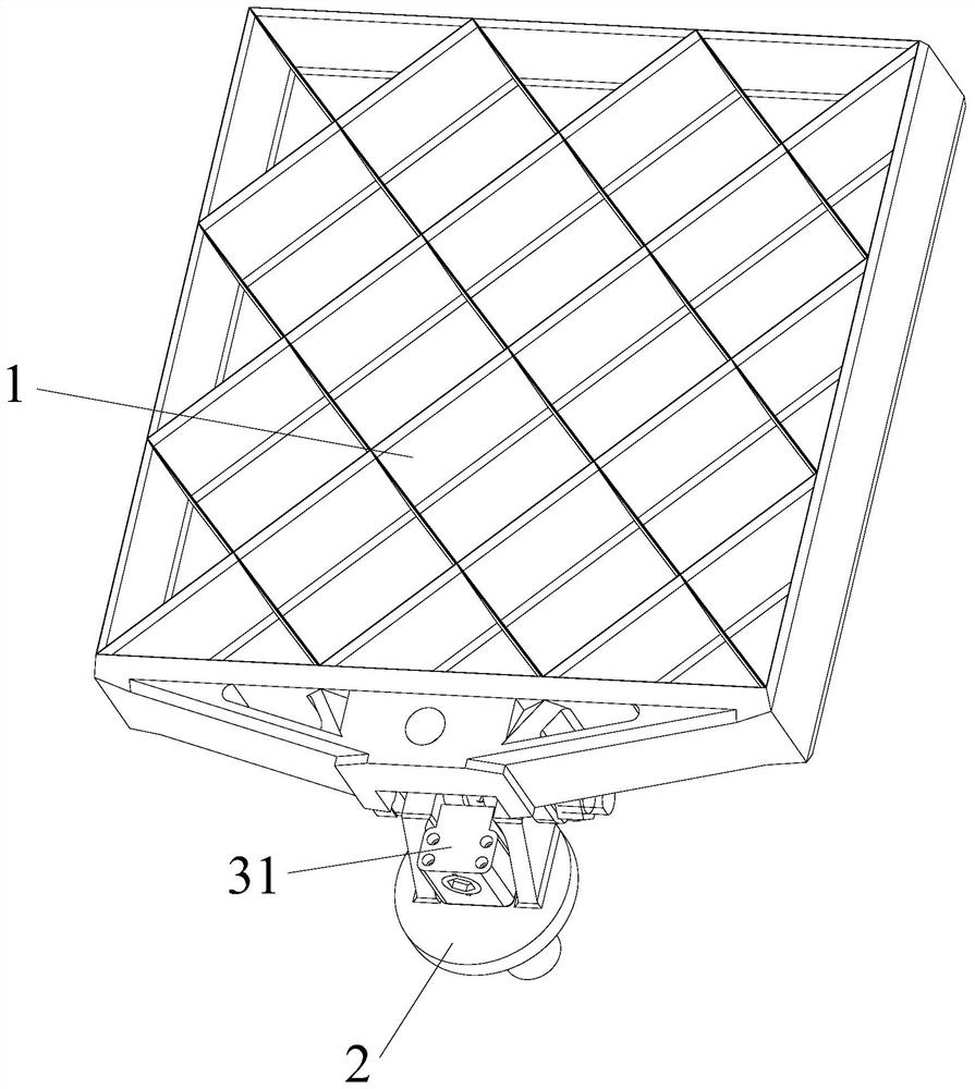
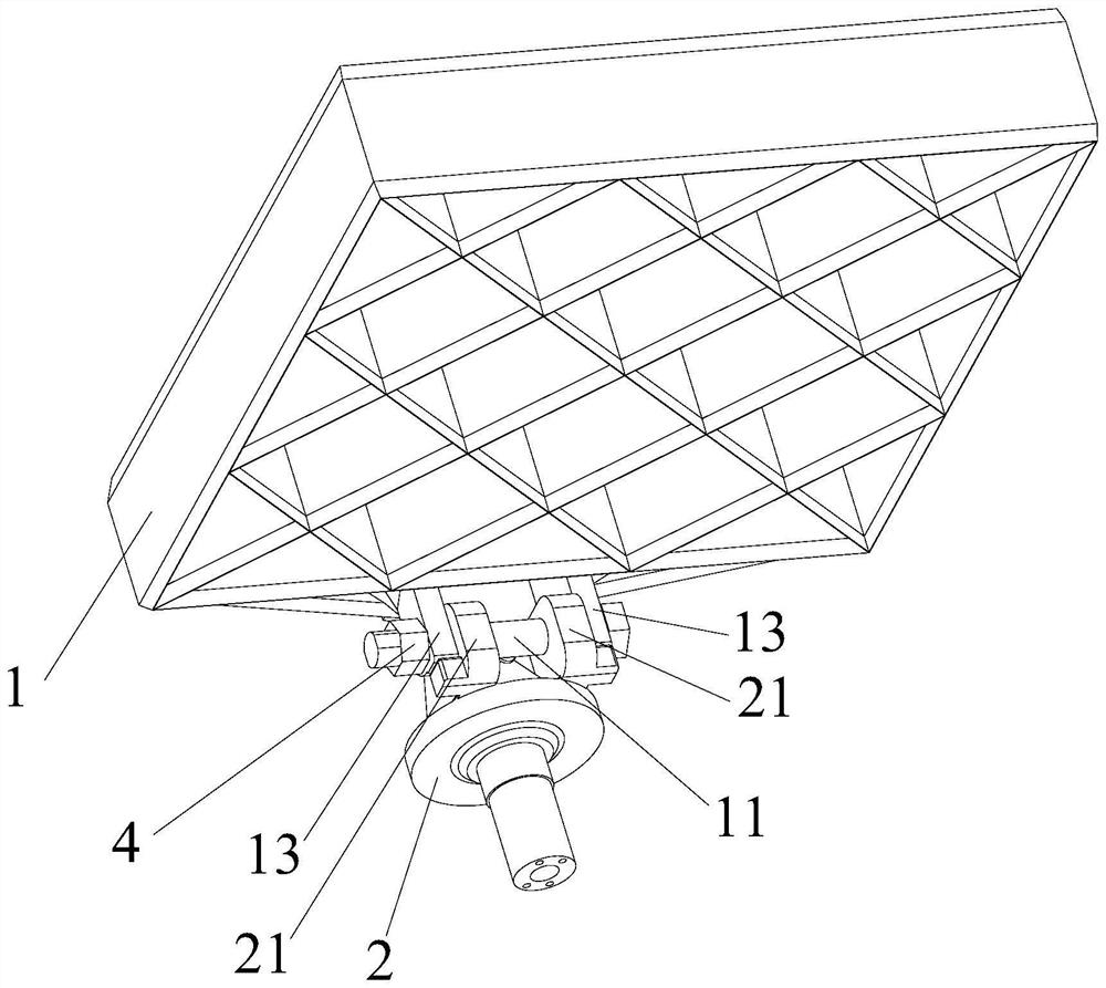
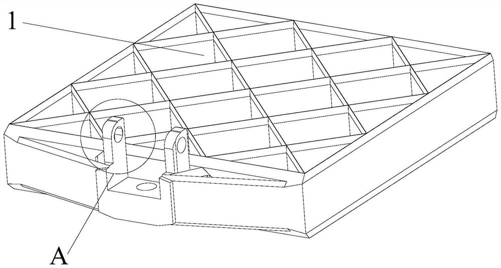
[0032] Such as Figure 1-8 As shown, an anti-rotation locking device includes a first body 1, a second body 2 and a locking mechanism located between the first body 1 and the second body 2, wherein:

[0033] The first main body 1 is provided with a rotating shaft 11 that rotates synchronously. When the first main body 1 rotates around the axis of the rotating shaft 11, the rotation angle of the first mai...


PUM


Abstract

The invention discloses an anti-rotation locking device which comprises a first main body and a second main body which are connected through a rotating shaft, and one side of the rotating shaft is provided with a locking mechanism comprising a base, an elastic piece and a locking part; when the first main body and the rotating shaft rotate at the same time, the elastic piece always ejects the locking part out of the opening towards the direction of the rotating shaft until the rotating shaft rotates to the locking position, and the side wall of the locking part is in contact with the first plane, so that continuous rotation of the rotating shaft is limited through the locking part, and rotation of the rotating shaft is prevented; meanwhile, the first main body synchronously rotating with the rotating shaft is prevented from rotating, on the premise that the second main body is fixed, the first main body can be quickly restrained to be kept in a locked state and does not rotate, and even in the irregular long-term vibration process, mutual limitation between the locking part and the first plane can be always kept through the action of the elastic piece; the locking state of the locking device is kept stable, and the locking reliability between parts of the aerospace vehicle is improved.

Description

technical field [0001] The present application relates to the technical field of aerospace vehicles, in particular to an anti-rotation locking device. Background technique [0002] In the field of space vehicles, many scenarios will face the problem of mechanism locking. Due to the special application environment of the space vehicle, higher requirements are put forward for the structure complexity, locking reliability, compactness and unlocking difficulty of the locking mechanism. [0003] At present, the locking mechanism mainly adopts the scheme of spring, cylindrical pin and connecting rod mechanism. After the spring and cylindrical pin scheme is locked, under the vibration condition caused by the high-speed movement of the space vehicle, the locking device between the mechanisms is prone to the rotation of the connecting mechanism, which will lead to the failure of the locking, and the occurrence of problems between the structures that need to be locked. The situation...

Claims


Application Information

Patent Timeline
Patent Type & Authority Applications(China)
IPC IPC(8): B64G1/22B64G1/64
Inventor 陈威翟海涛代志刚徐国伟王梓尧
Owner AEROSPACE SCI & IND KET TECH CO LTD
Learn More