Conveyor belt tension adjusting device, encoder damping device and use method of encoder damping device
A technology for tensioning adjustment and conveyor belts, applied in conveyors, transportation and packaging, non-rotational vibration suppression, etc., can solve problems such as ineffective tensioning of conveyor belts, inaccurate detection, and inconsistency between encoder feedback values and actual values. The effect of reducing the frequency of observation and spot inspection, and protecting the service life
- Summary
- Abstract
- Description
- Claims
- Application Information
AI Technical Summary
Problems solved by technology
Method used
Image
Examples
Embodiment approach
[0086] According to a preferred embodiment of the present invention, the conveyor belt 11 is wide, and the wide type has better anti-elongation ability, but it is difficult to install; 12 skidding, more preferably the contact surfaces of the conveyor belt 11 and the driven pulley 8, the driving pulley 12 are toothed, or pitted, etc., to increase friction.
[0087] According to another preferred embodiment of the present invention, the conveyor belt 11 is a double-drive belt or a triple-drive belt, which is convenient for installation.
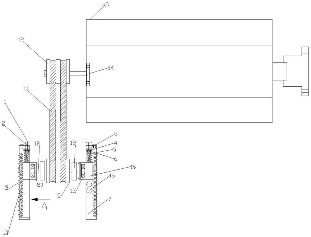
[0088] The second aspect of the present invention provides an encoder damping device, including an encoder 19, a driving wheel 12, a driven wheel 8 and a conveyor belt 11, the driven wheel 8 is located below the driving wheel 12, and the conveyor belt 11 is connected to The driving wheel 12 and the driven wheel 8, the driven wheel 8 is sleeved with a driven shaft 18; the conveyor belt tension adjustment device described in the first aspect is u...
Embodiment 1
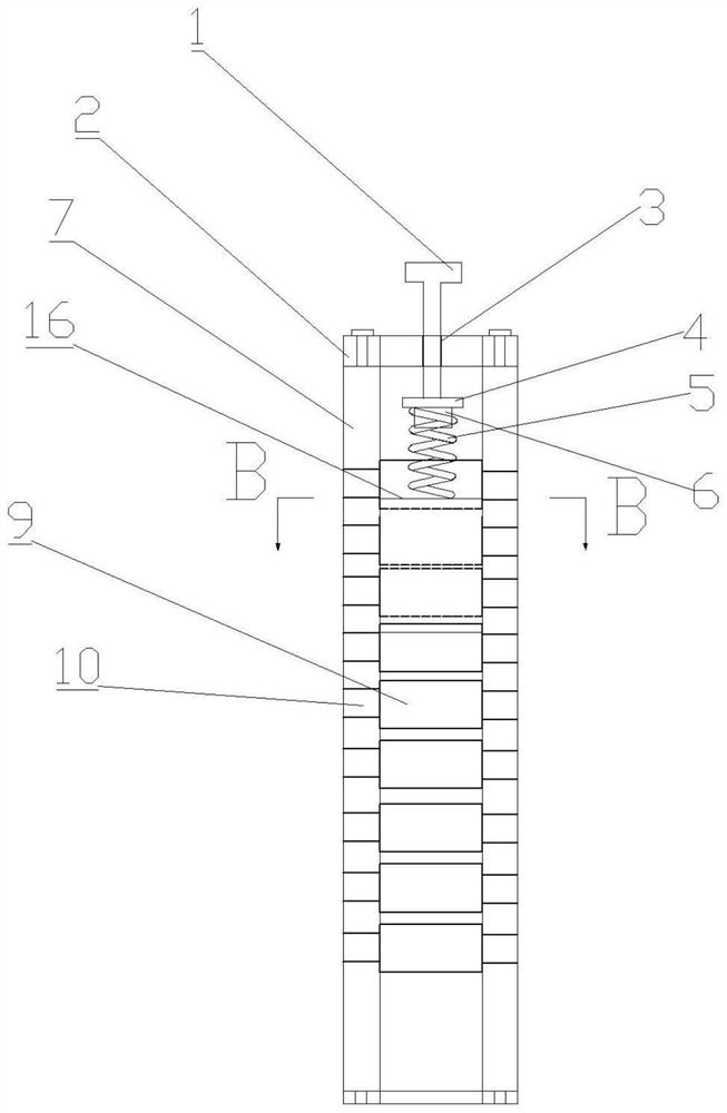
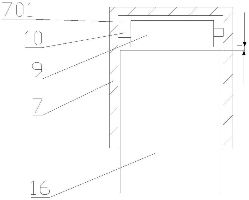
[0115] Encoder shock absorbers such as figure 1 As shown, the side bracket of the bracket 7 is fixedly arranged in a vertical state, and the sliding groove 701 on it is extended along the vertical direction.
[0116] According to the length and tension of the conveyor belt 11, the position of the bearing block 16 of the sliding part in the sliding groove 701 of the bracket 7 is adjusted by adjusting the relative position of the adjusting rod 1 and the pressing plate 2, so that the conveyor belt 11 remains in a tight state.
[0117] Its usage is as follows:
[0118] Start the motor 13, the motor 13 drives the driving wheel 12 to rotate through the connecting shaft 14, and the driving wheel 12 drives the conveyor belt 11 to drive the driven wheel 8 and the driven shaft 18 to rotate. The rotation of middle bearing seat 16. During the rotation, an encoder 19 mounted on the driven shaft 18 performs encoding.
[0119] During the rotation, when the conveyor belt 11 is elongated, b...
Embodiment 2
[0123] Encoder shock absorbers such as Figure 4 As shown, the two side brackets of the bracket 7 are fixedly arranged in an inclined state, and the sliding groove 701 on it extends along the inclined direction, and the bearing seat 16 is a trapezoidal body, and is installed in the sliding groove 701 . The structure of the elastic support mechanism 23 provided on the bracket 7 is the same as that of the tension elastic mechanism, including a threaded rod threaded on the second support frame 22, and a spring connected to the bottom of the threaded rod, and the bottom of the spring is connected to the side bracket and the bottom of the side support is hinged on the first support frame 21.
[0124] By adjusting the threaded rod of the elastic support mechanism 23 to cooperate with the spring connected to it, the side support maintains the required inclination angle (45°) in advance.
[0125] And, according to the length and the tension situation of conveyor belt 11 in advance, b...
PUM
 Abstract
Description
Claims
Application Information
 - R&D
- Intellectual Property
- Life Sciences
- Materials
- Tech Scout
- Unparalleled Data Quality
- Higher Quality Content
- 60% Fewer Hallucinations
Browse by: Latest US Patents, China's latest patents, Technical Efficacy Thesaurus, Application Domain, Technology Topic, Popular Technical Reports.
© 2025 PatSnap. All rights reserved.Legal|Privacy policy|Modern Slavery Act Transparency Statement|Sitemap|About US| Contact US: help@patsnap.com


