Debris bed breaker utilizing annular fluid

A technology of destroyer and cuttings bed, which is applied in the direction of cleaning equipment, wellbore/well components, directional drilling, etc., and can solve the problems of reduced service life of destroyer, deformation of destroyer, automatic adjustment of scraper and cuttings bed, etc. To achieve the effect of preventing the increase of pressure

Active Publication Date: 2022-04-12
NANTONG YONGDA PIPE IND
View PDF11 Cites 1 Cited by
  • Summary
  • Abstract
  • Description
  • Claims
  • Application Information

AI Technical Summary

Problems solved by technology

[0003] Most of the current cuttings bed destroyers are equipped with several groups of scrapers on the outer surface of the drilling tool, and the drilling tool drives the scrapers to destroy the cuttings bed in the well wall, but sometimes due to the existence of annular fluid , and a cuttings bed is formed in the well wall. If the cuttings bed destroyer is still working at this time, on the one hand, the service life of the destroyer will be reduced, and on the other hand, it may cause damage to the intact well wall. At the same time, the current cuttings The bed breaker cannot automatically adjust the distance between the scraper and the cuttings bed according to the thickness of the cuttings bed. If the feed rate of the scraper is too large when destroying the cuttings bed, the scraper will easily crack if the stiffness is unqualified. Dangerous, at the same time, after the scraper destroys the cuttings bed, it will produce larger cuttings bed debris, which is not conducive to the discharge of cuttings bed debris. In addition, during the drilling process, the well wall often collapses , it is difficult to deal with the collapsed cuttings bed, and if the delivery of drilling fluid cannot be stopped in time, the pressure in the borehole wall will be abnormally high, causing serious deformation or even rupture of the breaker. The current cuttings bed breaker is basically All kinds of sensors are used to detect the pressure inside the well wall, but the sensors often face problems such as poor contact or signal transmission, so that the service life of the current destroyer is not long

Method used


Image

  • Debris bed breaker utilizing annular fluid
  • Debris bed breaker utilizing annular fluid
  • Debris bed breaker utilizing annular fluid

Examples


Embodiment Construction

[0034] The following will clearly and completely describe the technical solutions in the embodiments of the present invention with reference to the accompanying drawings in the embodiments of the present invention. Obviously, the described embodiments are only some, not all, embodiments of the present invention. Based on the embodiments of the present invention, all other embodiments obtained by persons of ordinary skill in the art without making creative efforts belong to the protection scope of the present invention.

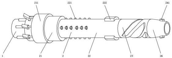
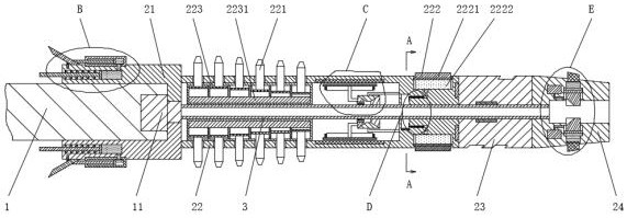
[0035] Such as Figure 1-10 As shown, a cuttings bed breaker using annular fluid includes a fixed rod 1 and a breaker body 2. The breaker body 2 includes a connecting pipe 21, a destroyer casing 22, a rotating pipe 23 and a drill bit 24. The connecting pipe 21 Set on the fixed rod 1, the destroyer casing 22 is fixedly installed on the end of the connecting pipe 21 away from the fixed rod 1 and several groups of third crushing heads 221 are arranged on the dest...


PUM


Abstract

The invention discloses a cuttings bed breaker using annulus fluid, which comprises a fixed rod and a breaker body, the breaker body comprises a connecting pipe, a breaker shell, a rotating pipe and a drill bit, the connecting pipe is arranged on the fixed rod, and the rotating pipe is arranged on the breaker shell. The breaker shell is fixedly installed at the end, away from the fixing rod, of the connecting pipe, and a plurality of sets of third breaking heads are arranged on the breaker shell. A detection device and a pressure sensing device are additionally arranged on an existing cuttings bed breaker, and the thickness of a cuttings bed can be detected through the detection device; the length, extending out of the destructor shell, of the third crushing head can be controlled through the magnetic field generator, the destructor body can be controlled to be connected with the fixing rod or the driving device through the air pump, and the purpose of destructing the cuttings bed can be achieved through the third crushing head and the destructor body; through the pressure sensing device, on one hand, drilling fluid can be prevented from entering the well wall, and on the other hand, the magnetic field generator and the air pump can work.

Description

technical field [0001] The invention relates to the technical field of drilling, in particular to a cuttings bed breaker utilizing annular fluid. Background technique [0002] With the development of the times, there are more and more directional wells of various types, but many problems will be encountered during the construction of directional wells. Cuttings are easy to fall from the well wall, and finally deposit on the lower side of the well wall to form a cuttings bed. Currently, when directional wells are being constructed, a cuttings bed destroyer is usually installed on the drill pipe. [0003] Most of the current cuttings bed destroyers are equipped with several groups of scrapers on the outer surface of the drilling tool, and the drilling tool drives the scrapers to destroy the cuttings bed in the well wall, but sometimes due to the existence of annular fluid , and a cuttings bed is formed in the well wall. If the cuttings bed breaker is still working, on the one...

Claims


Application Information

Patent Timeline
Patent Type & Authority Applications(China)
IPC IPC(8): E21B37/00E21B37/02E21B21/08E21B7/04
Inventor 徐培林
Owner NANTONG YONGDA PIPE IND
Why Eureka
Try Eureka