
GNSS mine reference point device and reference point health state monitoring method

A reference point and mine technology, applied in the direction of measuring devices, plumb lines, satellite radio beacon positioning systems, etc., can solve problems such as single function, reduced measurement accuracy, antenna signal transmission and reception blocking, etc., to reduce measurement errors, Reduce the transmission of measurement errors and increase the effect of extended functions

Active Publication Date: 2022-04-12
重庆华地资环科技有限公司
View PDF10 Cites 0 Cited by
  • Summary
  • Abstract
  • Description
  • Claims
  • Application Information

AI Technical Summary

Problems solved by technology

[0004] For the deficiencies of the above-mentioned technologies, the object of the present invention is to provide a GNSS mine reference point device and reference point health status monitoring method, in order to solve the problem of the single function of the reference point device in the prior art, and to install additional The equipment is easy to block the signal transmission and reception of the antenna, resulting in the reduction of its measurement accuracy

Method used


Image

  • GNSS mine reference point device and reference point health state monitoring method
  • GNSS mine reference point device and reference point health state monitoring method
  • GNSS mine reference point device and reference point health state monitoring method

Examples


Embodiment 2

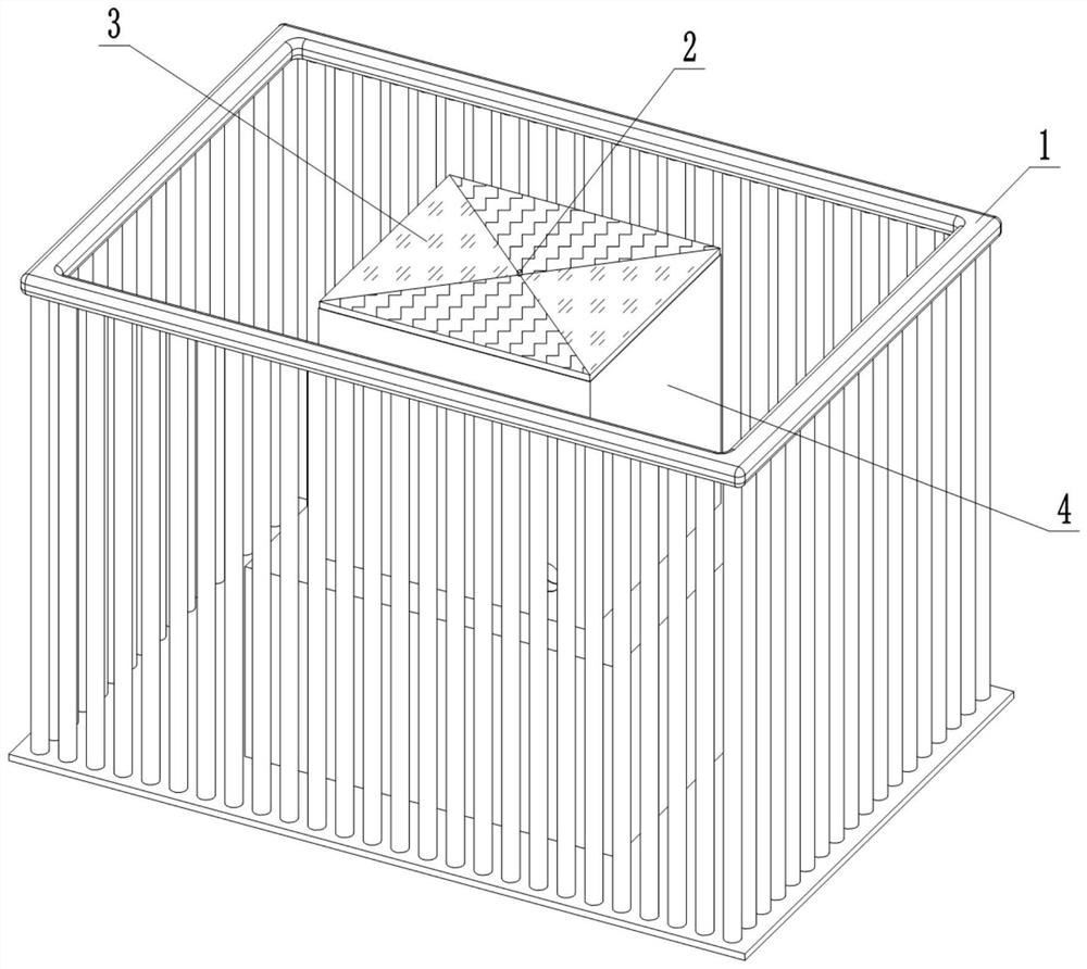
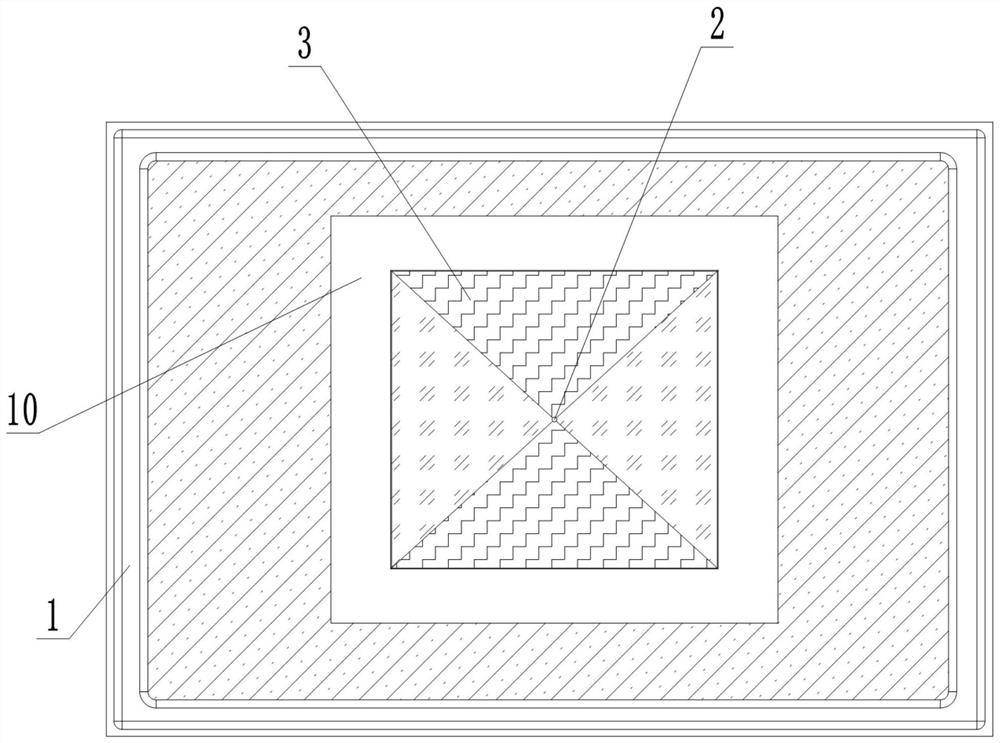
[0046] The difference between Embodiment 2 and Embodiment 1 is that the positional relationship between the equipment installation cavity 4 and the observation pier 10 is specifically that an installation groove is opened on the upper surface of the observation pier 10, and the bottom surface of the installation groove is in a horizontal state, and the equipment installation The lower installation cavity of the cavity 4 is fixed in the installation groove, which can make the fixing of the equipment installation cavity 4 more stable. Easy to be level.

Embodiment 3

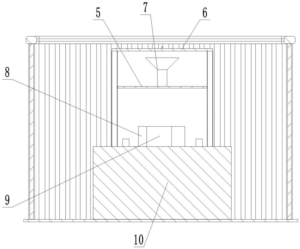
[0048] The difference between Embodiment 3 and Embodiment 1 lies in the installation method of the power supply system. Specifically, preferably, the power supply system includes a column, and the upper end of the column is provided with a mounting frame, and the mounting frame is provided with a solar panel fixedly connected thereto. , the bottom of the column is provided with a storage battery, and the storage battery, the solar panel and the control box 9 are electrically connected by installing the solar panel on the support, which can increase the height of the solar panel receiving sunlight and is not easily blocked.


PUM


Abstract

The invention relates to the technical field of mine control measurement, in particular to a GNSS mine datum point device and a datum point health state monitoring method. Comprising an observation pillar and an equipment installation cavity, the equipment installation cavity is fixedly connected with the observation pillar, a partition plate is arranged on the upper portion of the equipment installation cavity and divides the equipment installation cavity into an upper installation cavity and a lower installation cavity, a GNSS host and a control box are arranged in the lower installation cavity, a first wiring port is formed in one side face of the lower installation cavity, and a second wiring port is formed in the other side face of the lower installation cavity. The partition plate is provided with a second wiring port communicating the upper mounting cavity with the lower mounting cavity, a GNSS antenna is arranged in the upper mounting cavity, the lower end of the GNSS antenna is fixedly arranged in the middle of the partition plate, and the upper end face of the upper mounting cavity is a wave-transparent plate. The technical scheme is used for solving the problem of single function of a reference point device in the prior art and the problem that the measurement precision is reduced due to the fact that signal transmission and receiving of an antenna are blocked easily when additional equipment is installed on the reference point device.

Description

technical field [0001] The invention relates to the technical field of mine control and measurement, in particular to a GNSS mine reference point device and a reference point health status monitoring method. Background technique [0002] It is an inevitable trend of development to gradually realize the real-time and dynamic management of measurement marks based on the Internet-based measurement mark management information system. In the production process of surface mines, mine blasting, mine reserve verification, mine construction and other work are all based on datum points. In the past, mine datum points were generally fixed in rocks with screws or on cement piers. In order to realize the dynamic and information management of the reference point device, an antenna for receiving and transmitting signals needs to be added to the traditional reference point device. [0003] There are also some reference point devices with dynamic and information management functions on the ...

Claims


Application Information

Patent Timeline
Patent Type & Authority Applications(China)
IPC IPC(8): G01C15/08G01C15/10G01S19/14
Inventor 周珉羽张治清王宴会田茂强韩文友赵永辉程礼军高润霞周鹏
Owner 重庆华地资环科技有限公司
Features
  • Generate Ideas
  • Intellectual Property
  • Life Sciences
  • Materials
  • Tech Scout
  • Unparalleled Data Quality
  • Higher Quality Content
  • 60% Fewer Hallucinations
Learn More