Multifunctional electric automation equipment installation base

A technology for electrical automation and equipment installation, which is applied in mechanical equipment, non-rotational vibration suppression, cooling/ventilation/heating transformation, etc. It can solve the problems of easily damaged electrical automation equipment, the inability to adjust the position of the equipment in height, and the inability to adjust the position of the equipment by rotation , to achieve the effect of ensuring stability and protection, improving heat dissipation and cooling effect, and ensuring service life

Inactive Publication Date: 2019-07-19
周红军
View PDF9 Cites 10 Cited by
  • Summary
  • Abstract
  • Description
  • Claims
  • Application Information

AI Technical Summary

Problems solved by technology

[0007] In order to solve the above-mentioned technical problems, the present invention provides a multifunctional electrical automation equipment installation base to solve the problem that the existing electrical automation equipment installation base has an unsatisfactory heat dissipation effect, and the electrical automation equipment is easy to be damaged after being fixed, and the equipment cannot be rotated and adjusted. The problem of the position of the device and the inability to height adjust the position of the device

Method used


Image

  • Multifunctional electric automation equipment installation base
  • Multifunctional electric automation equipment installation base
  • Multifunctional electric automation equipment installation base

Examples


Embodiment Construction

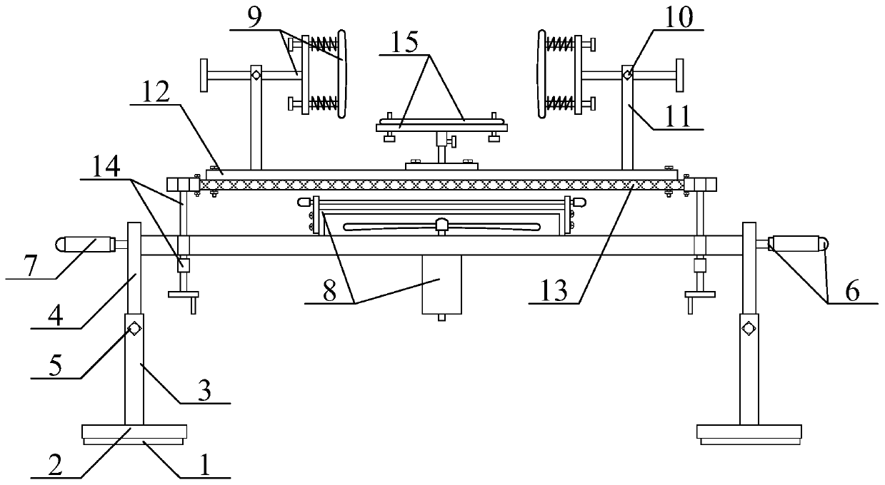
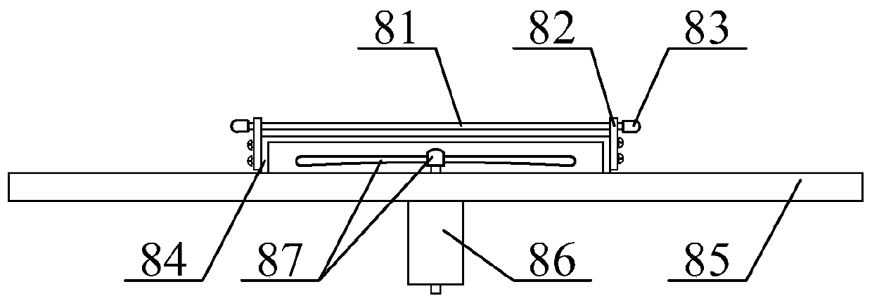
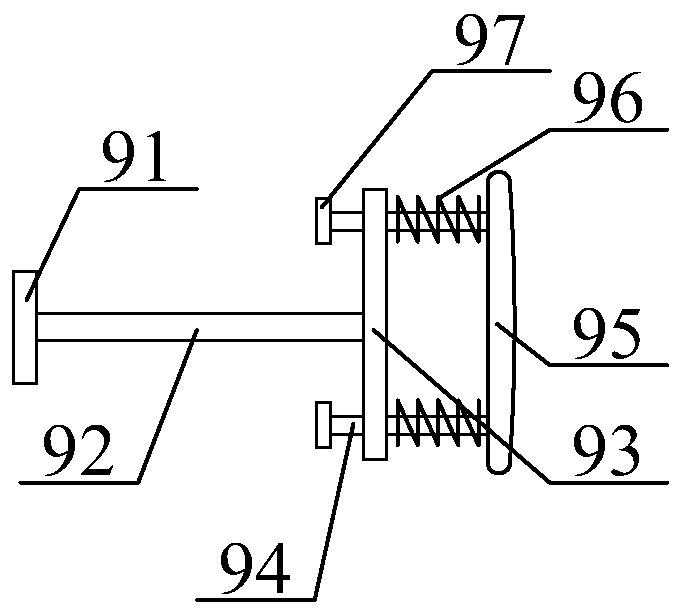
[0045] The present invention is described in detail below in conjunction with accompanying drawing, as appended figure 1 And attached figure 2 As shown, a multi-functional electrical automation equipment installation base includes an anti-skid pad 1, a support base 2, a fixed pipe 3, a telescopic rod 4, an adjustment bolt 5, an auxiliary handle 6, a protective cover 7, and an auxiliary cooling fan 8 for cooling equipment. , the anti-injury buffer clamping frame 9, the fixing bolt 10, the support liner 11, the connection liner 12, the hollow seat 13, the height auxiliary adjustable equipment mounting seat structure 14 and the auxiliary equipment rotation adjustment fixed base structure 15, the described The anti-skid pads 1 are respectively transversely glued to the middle position of the upper surface of the support base 2; the inner middle positions of the support base 2 are respectively threaded to the lower end of the fixed pipe 3; the longitudinal upper parts of the fixed...


PUM


Abstract

The invention provides a multifunctional electric automation equipment installation base which comprises an anti-skid pad, a support base, a fixed pipe, a telescopic rod, an adjusting bolt, an auxiliary handle, a protective sleeve, an air-cooling fan capable of assisting equipment in radiating, an anti-injury buffer clamp mounting frame, a fixing bolt, a supporting lining seat, a connecting liningseat, a hollowing seat, a structure capable of highly assisting in adjusting the equipment installation base and a structure capable of assisting the equipment in rotation, adjusting and fixing the base. Through the arrangement of a cold air pipe and a rubber cap, an appropriate amount of cooling liquid can be injected into the cold air pipe according to the actual operation, the rubber cap is sealed and fixed, and the cooling effect of the equipment can be improved, and the service life of the equipment is ensured; a heat dissipating motor and fan blades are arranged, so that rotation of thefan blades is better driven by the heat dissipating motor, air is continuously blown upwards, cooling and heat dissipating work are continuously done on the equipment along with the cooling air discharged from the cold air pipe, the heat-dissipating and cooling effects of the equipment are improved, and the working state of the equipment is ensured.

Description

technical field [0001] The invention belongs to the technical field of electrical automation equipment, and in particular relates to a multifunctional electrical automation equipment installation base. Background technique [0002] The base of electrical automation is often installed in the electrical cabinet according to the actual installation situation. The general electrical automation base is processed and manufactured through compression molding. The heat dissipation performance of the existing electrical automation installation base is poor. As a result, the electrical automation equipment cannot get the proper cooling, which shortens the service life of the electrical automation equipment. Secondly, electrical automation equipment of different sizes needs to be installed on electrical automation installation bases of different sizes. However, the electrical automation in the electrical cabinet There are many equipments, which leads to the disorderly installation of t...

Claims


Application Information

Patent Timeline
Patent Type & Authority Applications(China)
IPC IPC(8): F16M11/04F16F15/04F16M11/08F16M11/16H05K7/20
CPCF16F15/04F16M11/04F16M11/046F16M11/08F16M11/16H05K7/20
Inventor 周红军黄辉
Owner 周红军
Why Eureka
Try Eureka