Sliding rail lamp connecting sleeve

A technology for connecting sleeves and slide rail lights, which is applied in the direction of connecting, engaging/disconnecting connecting parts, coupling devices, etc., and can solve problems affecting the use of lamps, power failure, and loose electric needles, etc.

Pending Publication Date: 2022-04-12
董文彬
View PDF0 Cites 0 Cited by
  • Summary
  • Abstract
  • Description
  • Claims
  • Application Information

AI Technical Summary

Problems solved by technology

However, through the electric connection between the electric needle and the slide rail, the electric needle is easy to loosen, causing a power outage and affecting the use of the lamp

Method used


Image

  • Sliding rail lamp connecting sleeve
  • Sliding rail lamp connecting sleeve

Examples


Embodiment Construction

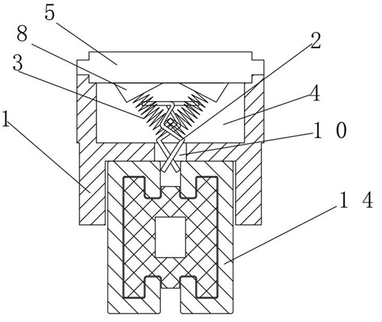
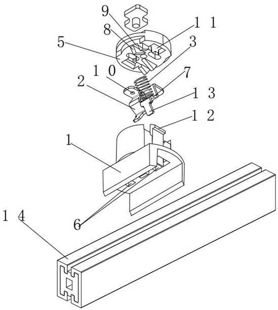
[0014] refer to figure 1 , figure 2 , a slide rail lamp connecting sleeve, including a sleeve body 1, a cavity 4 for accommodating a reed 2 and a spring 3 is provided on the sleeve body 1, a cover 5 is fixed on the cavity 4, and the reed 2 is curved One end of the spring 3 presses the inner wall of the cover 5, and the other end presses the reed 2, so that one end of the reed 2 extends outward through the through hole 6 of the sleeve body 1. Press the sleeve body 1 of the present invention on the slide rail 14, and the reed 2 will move into the cavity. When the free end of the reed moves above the groove in the middle of the slide rail, the reed will fall under the force of the spring. It will extend outward again, so that the free end 13 of the reed is pressed against the inner wall of the groove of the slide rail, so as to realize the electrical connection. Because the free end 13 of the reed is pressing the slide rail under the active force of the spring, therefore, the ...


PUM


Abstract

The invention discloses a sliding rail lamp connecting sleeve which comprises a sleeve body, a cavity for containing a reed and a spring is formed in the sleeve body, a sealing cover is fixed to the cavity, the reed is bent, one end of the spring presses the inner wall of the sealing cover, the other end of the spring presses the reed, and one end of the reed penetrates through a through hole of the sleeve body to extend outwards. The sleeve body is pressed on the sliding rail, the reed can move into the cavity, when the free end of the reed moves to the position above the groove in the middle of the sliding rail, the reed can extend outwards again under the acting force of the spring, and therefore the free end of the reed presses the inner wall of the groove of the sliding rail, and electric connection is achieved. Due to the fact that the free end of the reed presses the sliding rail under the acting force of the spring, the reed and the sliding rail are in contact all the time under the acting force of the spring, no gap or loosening exists, and the power failure phenomenon is avoided.

Description

technical field [0001] The invention relates to a connecting device of a slide rail lamp, in particular to a connecting sleeve. Background technique [0002] The existing slide rail light connecting sleeve includes a sleeve body, and the sleeve body is provided with positive and negative electric needles. Thereby realizing electrical connection. However, if the electric needle is electrically connected to the slide rail, the electric needle is likely to loosen, causing a power outage and affecting the use of the lamp. Contents of the invention [0003] In order to overcome the above-mentioned problems, the object of the present invention is to provide a sliding track light connecting sleeve with stable connection and no power failure. [0004] The present invention achieves the above object like this: [0005] A connecting sleeve for a slide rail light, comprising a sleeve body, a cavity for accommodating a reed and a spring is provided on the sleeve body, a cover is fi...

Claims


Application Information

Patent Timeline
Patent Type & Authority Applications(China)
IPC IPC(8): H01R25/14H01R13/62F21V23/06F21V21/35
Inventor 董文彬
Owner 董文彬
Why Eureka
Try Eureka