
Electric lamp with comparatively robust lamp cap

A technology for lamp holders and electric lamps, which is applied to circuits, incandescent lamps, electrical components, etc., and can solve the problems of end, damage to lamp holders, and high cost

Inactive Publication Date: 2004-03-24
KONINKLIJKE PHILIPS ELECTRONICS NV
View PDF1 Cites 0 Cited by
  • Summary
  • Abstract
  • Description
  • Claims
  • Application Information

AI Technical Summary

Problems solved by technology

This increases the risk of deformation of the cone of the metal shell, e.g. deformation of the insulating material, which could damage the lamp cap and remove contact between the bottom contact piece and the second electrical contact, thus prematurely ending the lamp life
[0010] A disadvantage of the known lamp is its high cost, since the metal shell requires relatively much material if it is formed strong enough to withstand a certain axial pressure at or above a lower limit

Method used


Image

  • Electric lamp with comparatively robust lamp cap
  • Electric lamp with comparatively robust lamp cap
  • Electric lamp with comparatively robust lamp cap

Examples


Embodiment Construction

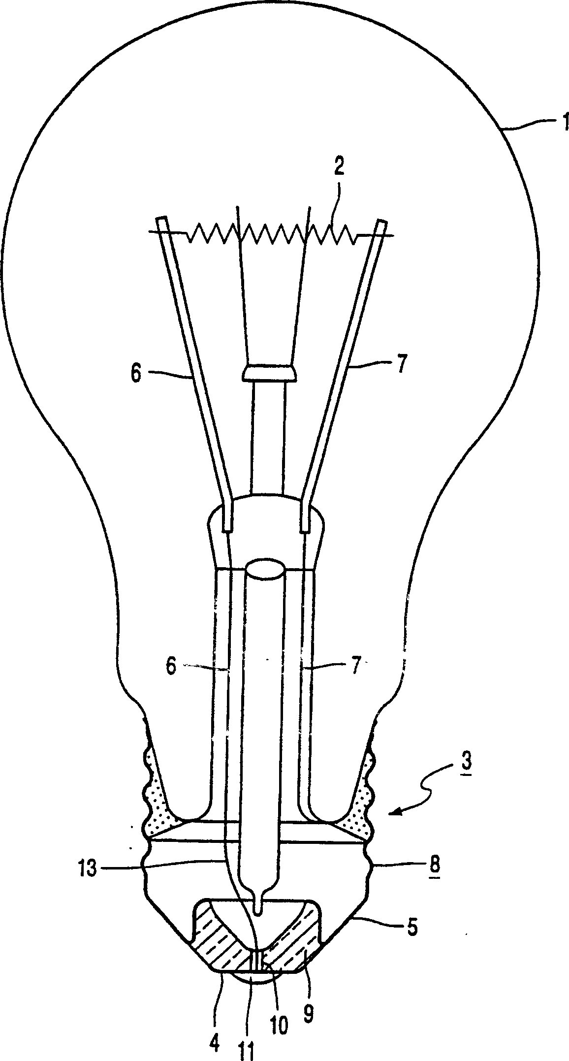
[0027] exist figure 1 , 2, 3 and 4, corresponding parts are given the same reference signs. figure 1 In , an electric lamp has a lamp vessel 1 in which a light source 2 is arranged, the light source shown in the figure being an incandescent body. The lamp cap 3 is connected with the lamp container 1, and the lamp cap in the figure is an Edison lamp cap. The supply conductors 6 , 7 are connected to respective contacts 4 , 5 of the light source 2 and of the lamp cap 3 . The lamp cap has a metal shell 8 forming a first electrical contact 5 and a base 9 of insulating material such as mirror glass. The base 9 supports a metal disc forming the second electrical contact 4 . The current supply conductor 6 leads to the outside through the base 9 and the opening 10 in the metal disc, where it is fixed to the metal disc, for example soldered or fixed thereto using solder 11 for example.

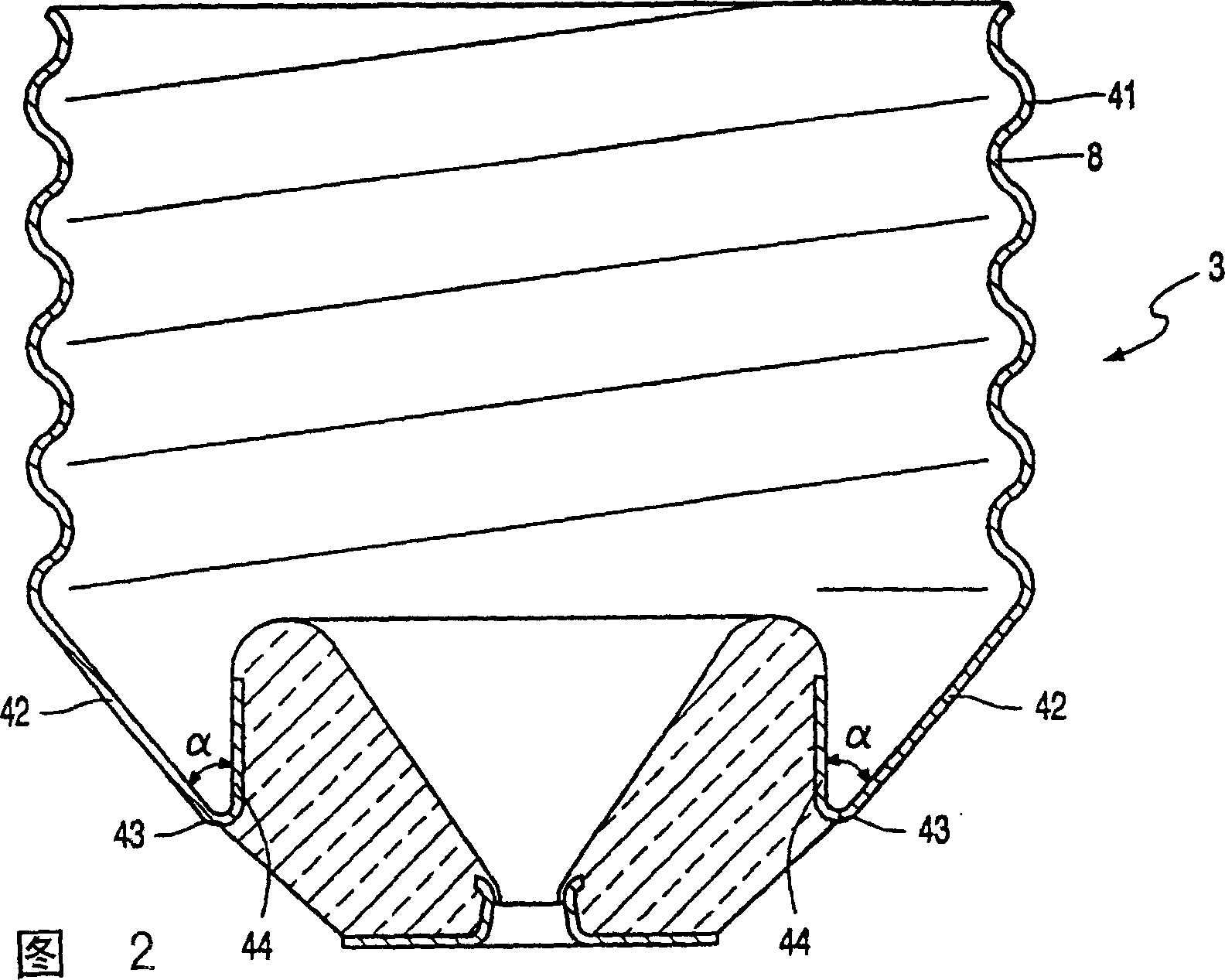
[0028] In FIG. 2 , the metal shell 8 of the cap 3 of the known lamp has a threaded portion 41 co...


PUM


Abstract

The electric lamp is provided with a cap (3) having a metal shell (8). The shell (8) comprises a cylindrical part (44) which is coupled to a conical part (42) via a rounding (43). By choosing the angle beta between the second part (52) of the conical part (42) and the cylindrical part (44) smaller than the angle alpha between the first part (51) of the conical part (42) and the cylindrical part (44), the axial strength of the metal shell (8) is increased.

Description

technical field [0001] The invention relates to an electric lamp comprising: [0002] the lamp vessel in which the light source is installed; [0003] Lamp caps connected to lamp vessels and provided with electrical contacts; [0004] supply conductors connected to the contacts of the light source and lamp cap; [0005] Said cap comprises a metal shell 8 having a threaded portion 41 connected via a cone 42 to a cylindrical portion 44 concentric with said threaded portion 41 and surrounded by said cone 42, form an angle with the cone 42, [0006] The invention also relates to a base for use in said lamp. Background technique [0007] Such lamps are generally known and described, for example, in EP 0 488 462 . The base of the lamp may be of the Edison type. The lamp cap comprises a metal shell forming a first electrical contact, and a base of insulating material, eg glass, such as vitrite glass, which supports a metal disc forming a second electrical contact. [0008] T...

Claims


Application Information

Patent Timeline
IPC IPC(8): H01K1/46
CPCH01K1/46
Inventor P·C·凯姆H·J·特卢
Owner KONINKLIJKE PHILIPS ELECTRONICS NV
Features
  • Generate Ideas
  • Intellectual Property
  • Life Sciences
  • Materials
  • Tech Scout
  • Unparalleled Data Quality
  • Higher Quality Content
  • 60% Fewer Hallucinations
Learn More