Flow chamber

a flow chamber and microscopic technology, applied in the field of flow chambers for lightoptical microscopic and lightspectroscopic examinations, can solve the problems of poor optical properties of most plastic materials, risk of air bubble formation in the flow system, and plastic containers are hardly used for this type of examination, so as to prevent or minimize the deformation of the chamber, mechanically stabilize the flow chamber, and facilitate the effect of manufacturing

Active Publication Date: 2005-01-27
IBIDI
View PDF10 Cites 27 Cited by
  • Summary
  • Abstract
  • Description
  • Claims
  • Application Information

AI Technical Summary

Benefits of technology

[0028] According to an advantageous embodiment, the flow chamber is formed as an injection molding element. This leads to an especially simple and inexpensive manufacturing mode.
[0029] According to a further advantageous development, a frame is arranged on the surface of the base plate, at which the at least one channel is provided. The frame may particularly be arranged along the entire circumference or along part of the circumference of the base plate. This enables a precise arrangement of the cover on the base plate. The height of the frame may be equal to the thickness of the cover. According to a preferred alternative, the frame is higher than the thickness of the cover, which is why the frame also serves as a spacer, which prevents the cover from being scratched. The frame preferably has a height of between 1 μm and 1 mm and a width of 1 μm and 1 mm. A further advantage of the frame is that it mechanically stabilizes the flow chamber and particularly prevents or minimizes a deformation of the chamber when cooling in an injection mold.
[0030] According to a preferred alternative, the cover comprises a frame. A foil is for instance clamped on or in a frame. This cover may fixedly be connected to the base plate of the flow chamber and may stabilize this flow chamber.
[0031] According to an advantageous embodiment, at least one liquid reservoir is formed in a manner that in the case of a closed input and output opening of the channel connected, a plug means can be inserted into the liquid reservoir for the air-tight lock. A plug means for the air-tight lock is a plug means which, when being engaged with the liquid reservoir, may close this reservoir in an air-tight manner. When inserting such a plug means, e.g. a filled pipette, the air displaced through this from the liquid reservoir may escape to the outside even if the channel connected is filled with liquid. An opening for ventilation arranged laterally in the liquid reservoir at a suitable height is a possibility offered. According to a preferred alternative, the liquid reservoir is formed in a manner expanding conically towards the opening. Liquid reservoirs of this type offer the advantage that plug means for air-tight locking may be inserted without the existing liquid level being changed as long as the plug means is above the liquid level. The liquid level and / or the shape of the liquid reservoir is preferably chosen such that the plug means is engaged above the liquid level with the liquid reservoir, that particularly the liquid is at most touched but not submersed into the liquid.
[0032] According to an advantageous embodiment of all above-described flow chambers, at least one input or output opening of a channel is arranged on a predetermined level of a liquid reservoir. This on the one hand has the advantage that only as of a certain liquid level the liquid may flow into the channel. On the other hand, a predetermined liquid level can be adjusted in other liquid reservoirs according to the principle of the communicating pipes.

Problems solved by technology

Plastic containers are hardly used for this type of examination due to the poor optical property of most of the plastic materials (compared to glass).
This includes the risk of the formation of air bubbles in the flow system.
Experience shows that this often leads to leakage and to the fact that molecules in the solution change their functional structure due to a contact with the seal ring, or that they absorb to the seal ring.
However, the micro-channel is not used for rinsing through liquids or for high-resolution microscopy.
The acrylic glass does also not have sufficiently favorable optical properties to carry out high-class microscopy.
Most of the techniques with conventional sample chambers only allow a quantitative but not a qualitative analysis of the signals.
Moreover, excessive molecules may weaken or extinguish the fluorescence signal or spectrum of the molecule or molecule complex to be examined.

Method used


Image

  • Flow chamber
  • Flow chamber
  • Flow chamber

Examples


Embodiment Construction

[0011] It is the object of the present invention to develop a flow chamber, which allows a quick and simple flow and exchange of liquids, which moreover enables a trouble-free implementation of the above-mentioned examinations and by means of which the quantity of verification molecules required for an examination can be reduced. Furthermore, a flow chamber is to be provided, which is simple to manufacture and to operate.

[0012] A further object of the invention is to provide a method, which facilitates the implementation of the above-mentioned examination methods and which discloses new examination possibilities.

[0013] This object is solved by a flow chamber according to the characterizing features of claim 1 and by the method according to claim 16. Advantageous embodiments can be derived from the dependent claims.

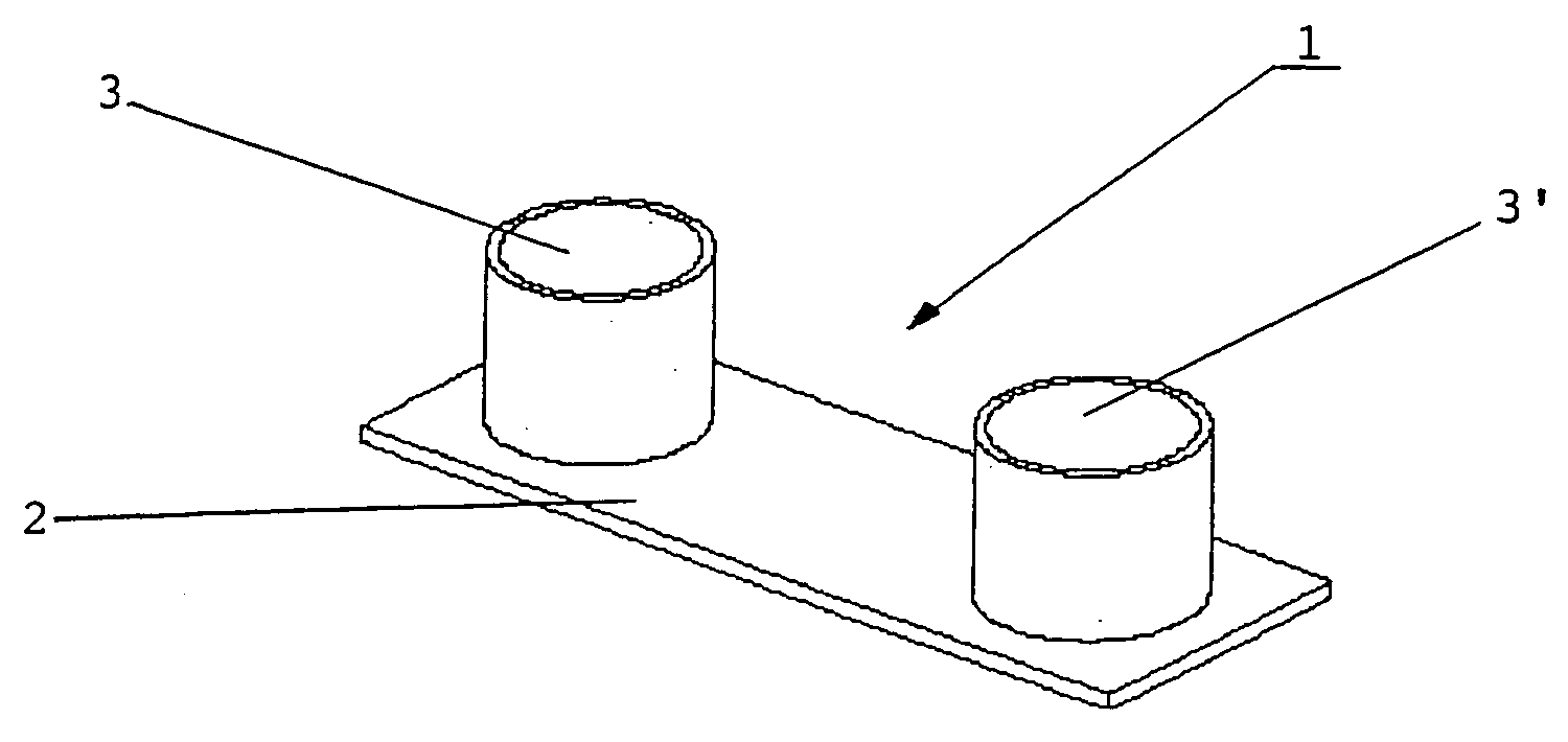
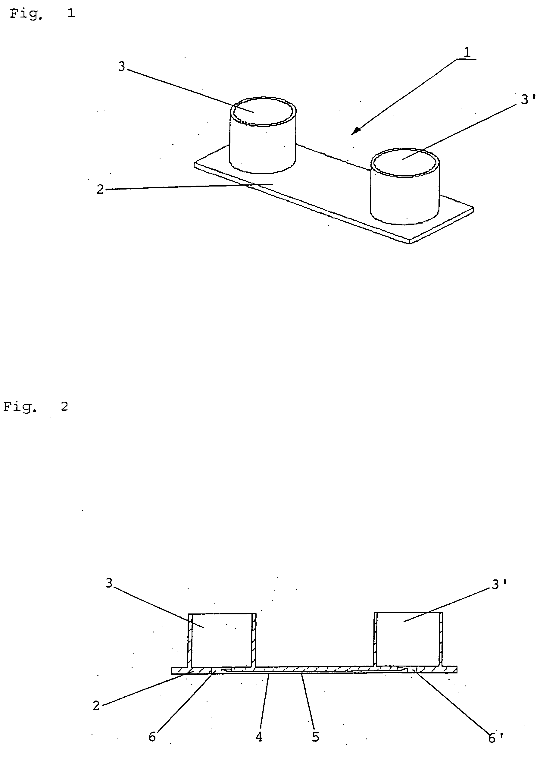
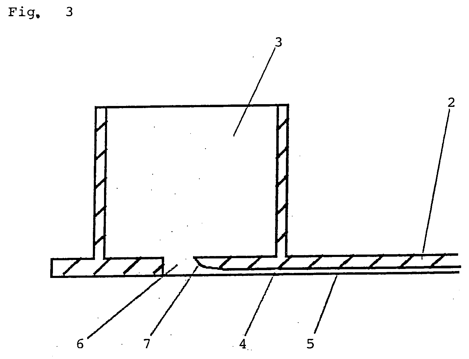
[0014] According thereto, a flow chamber made of plastics as an object carrier for light-optical microscopic examinations comprises at least one channel in a base plate...


PUM

PropertyMeasurementUnit
heightaaaaaaaaaa
widthaaaaaaaaaa
thicknessaaaaaaaaaa

Abstract

A flow chamber (1) made of plastics as an object carrier for light-microscopic examinations comprised at least one channel (4) in a base plate (2), said channel having a width of 0.01 to 20 mm and a height of 0.01 to 5 mm. One liquid reservoir (3, 3′) each is connected to the inlet and outlet opening (6, 6′) of the channel, whereby a communicating system is generated. The bottom and/or the cover of this chamber is made of a high-class plastic material and may be functionalized. The inlet and outlet portions of the channel may be formed by a rounding (7) of the channel edges or by a surface treatment in a manner that drop formation is prevented and the flow is therefore not obstructed. In a method of sample preparation for light-optical microscopic examinations, a sample flow is generated by a system of communicating pipes, in that a reservoir of a solution with the sample is connected via a third channel with at least one further reservoir and the filling level of the reservoirs differs at the beginning of the examination.

Description

FIELD OF THE INVENTION [0001] The present invention refers to a flow chamber for light-optical microscopic and light-spectroscopic examinations according to the preamble of claim 1 and to a method for the preparation of samples for light-optical microscopic examinations according to claim 16. [0002] The invention particularly refers to a flow chamber by means of which movable and immovable molecules, macromolecules or cells can be examined by different light-optical microscopic and spectro-optical techniques (e.g. high-resolution microscopy, fluorescence microscopy, phase contrast microscopy, confocal microscopy, etc.). PRIOR ART [0003] Object carriers and Petri dishes for samples to be examined are used in the most variable examination methods and must therefore meet many different demands. Many biological-medical examinations are for instance carried out by the aid of light-optical microscopic and / or spectroscopic techniques. Besides the pure light-optical microscopy (e.g. for the...

Claims


Application Information

Patent Timeline
Patent Type & Authority Applications(United States)
IPC IPC(8): B01L3/00G01N1/00G01N21/05G02B21/34
CPCB01L3/5025B01L3/5027B01L3/502715B01L2200/027G02B21/34B01L2300/0877B01L2300/12B01L2400/0406B01L2400/0457B01L2300/0822
Inventor KAHL, JOHAN VALENTIN
Owner IBIDI
Why Eureka
Try Eureka