Piping rounding mode bits with floating point instructions to eliminate serialization

a floating point instruction and rounding mode technology, applied in the field of microprocessors, can solve the problems of low rounding mode performance, difficult to change the rounding mode of other algorithms, and the performance of other algorithms that change the rounding mode often suffers the same degradation

Inactive Publication Date: 2001-05-15
ADVANCED MICRO DEVICES INC
View PDF23 Cites 26 Cited by
  • Summary
  • Abstract
  • Description
  • Claims
  • Application Information

AI Technical Summary

Benefits of technology

FIG. 9 is a block diagram of on

Problems solved by technology

Floating point data types produce challenges for the microprocessor designer.
Unfortunately, certain algorithms rely on repeatedly changing the rounding mode of the floating point unit.
Therefore, t

Method used


Image

  • Piping rounding mode bits with floating point instructions to eliminate serialization
  • Piping rounding mode bits with floating point instructions to eliminate serialization
  • Piping rounding mode bits with floating point instructions to eliminate serialization

Examples


first embodiment

Turning next to FIG. 5, portions of FPU 36 are shown illustrating the conveyance of a rounding mode with each instruction through the execution pipeline of FPU 36. FPU control unit 92, FPU core 94, FPU environment 88, and assembly queue 80 are shown. A first entry of assembly queue 80 is illustrated via an opcode storage 110, a register specifier storage 112, and a memory operand storage 114. Similar opcode storage, register specifier storage, and memory operand storage locations are included in assembly queue 80 for storing other instructions. Additionally, assembly queue 80 includes a control unit 116 and a rounding mode storage 118. FPU environment 88 includes a control word register 120. Additionally, several pipeline stages 122A-122D are illustrated within FPU control unit 92. Each pipeline state 122A-122D includes a field 124 for storing instruction information (e.g. opcode, operand information, etc.) and a field 126 for storing the rounding mode applicable to the instruction....

second embodiment

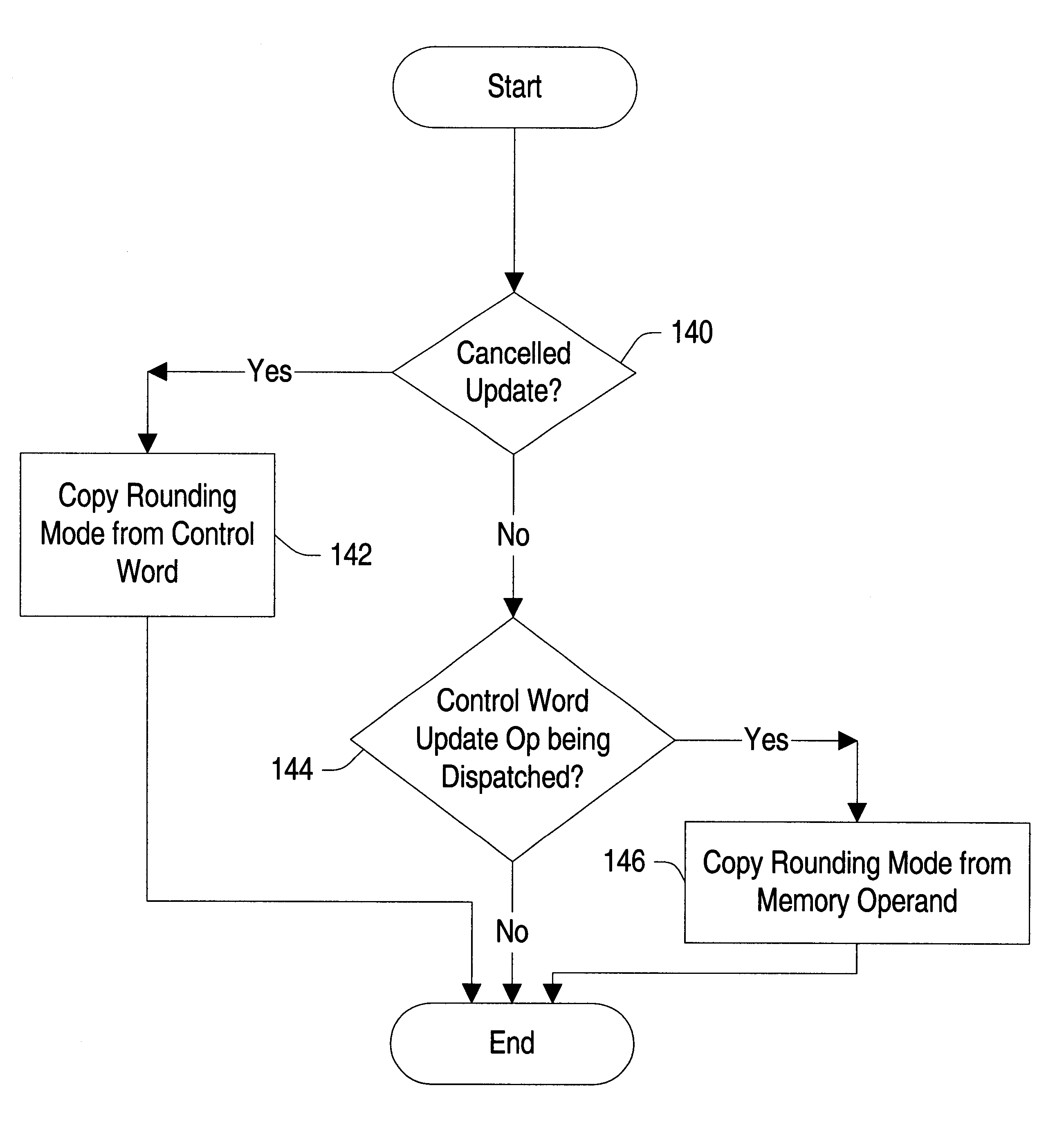
Turning now to FIG. 6, portions of FPU 36 are shown illustrating the conveyance of a rounding mode with each instruction through the execution pipeline of FPU 36. FPU control unit 92, FPU core 94, FPU environment 88, and translate unit 82 are shown. Translate unit 82 includes a control unit 130 and a rounding mode storage 132. FPU environment 88 includes control word register 120, as shown in FIG. 6 above. Additionally, FPU control unit 92 includes several pipeline stages 122A-122D, each including a field 124 for storing instruction information (e.g. opcode, operand information, etc.) and a field 126 for storing the rounding mode applicable to the instruction. FPU core 94 includes a pipeline as well, and as an alternative to storing the rounding mode in FPU control unit 92, the rounding mode may be pipelined within FPU core 94. Control unit 130 is coupled to rounding mode storage 132. Control unit 130 receives a cancel CW update signal upon conductor 128, and further receives the op...


PUM


Abstract

A floating point unit is provided which conveys the rounding mode in effect upon dispatch of a particular instruction with that particular instruction into the execution pipeline of the floating point unit. Upon dispatch of a control word update instruction into the execution pipeline, the rounding mode is updated according to the updated control word provided for the control word update instruction. Instructions subsequent to the control word update instruction thereby receive the updated rounding mode as those instructions are dispatched. The updated rounding mode is available to the subsequent instructions prior to retiring the control word update instruction. The rounding mode is therefore updated without serializing the update. If the control word update instruction modifies the value in a field other than the rounding mode, the instructions subsequent to the control word update instruction may be discarded and re-executed subsequent to updating the control word register with the updated control word. In this manner, the control word update is effectively serialized for cases in which a field other than the rounding mode is updated.

Description

1. Field of the InventionThis invention relates to the field of microprocessors and, more particularly, to the handling of rounding modes within floating point units of microprocessors.2. Description of the Related ArtSuperscalar microprocessors achieve high performance by executing multiple instructions per clock cycle and by choosing the shortest possible clock cycle consistent with the design. As used herein, the term "clock cycle" refers to an interval of time accorded to various stages of an instruction processing pipeline within the microprocessor. Storage devices (e.g. registers and arrays) capture their values according to the clock cycle. For example, a storage device may capture a value according to a rising or falling edge of a clock signal defining the clock cycle. The storage device then stores the value until the subsequent rising or falling edge of the clock signal, respectively. The term "instruction processing pipeline" is used herein to refer to the logic circuits ...

Claims


Application Information

Patent Timeline
IPC IPC(8): G06F9/302G06F9/30G06F9/38G06F9/318G06F7/48
CPCG06F9/30076G06F9/30087G06F9/30152G06F9/30189G06F9/3816G06F9/382G06F9/3822G06F9/3861G06F9/30014G06F7/483G06F7/49957
Inventor LYNCH, THOMAS W.
Owner ADVANCED MICRO DEVICES INC
Why Eureka
Try Eureka