

Comparator-based high-precision edge detection method and system
An edge detection and comparator technology, applied in multiple input and output pulse circuits, pulse description, etc., can solve the problems that errors cannot be eliminated through calibration, resistance error calibration, and rise time does not change, so as to improve edge detection accuracy, The effect of avoiding precision errors and eliminating influences
- Summary
- Abstract
- Description
- Claims
- Application Information
AI Technical Summary
Problems solved by technology
Method used
Image

Examples
Embodiment 1
[0075] Embodiment 1 of the present invention discloses a high-precision edge detection method based on a comparator. The edge detection is performed by acquiring an actual level value to reduce the influence of the precision caused by the resistance. Method flow chart instruction attached Figure 4 As shown, the specific scheme is as follows:
[0076] A high-precision edge detection method based on a comparator, applicable to a system including ATE test equipment, a device under test and a transmission line, the ATE test equipment and the device under test are connected through a transmission line, and an FPGA is arranged in the ATE test equipment and a test module, the FPGA is connected to the test module, and the test module is provided with a comparator.
[0077] The methods specifically include:
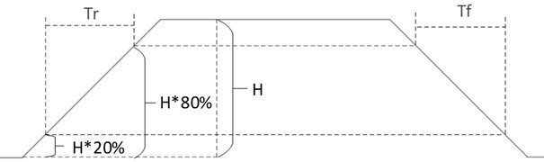
[0078] 101. Level estimation: Obtain the waveform to be tested output by the device under test, and estimate the waveform to be tested to obtain the low level value and the hig...
Embodiment 2
[0111] Embodiment 2 of the present invention discloses a comparator-based high-precision edge detection system. On the basis of embodiment 1, the method of embodiment 1 is systematized, and the specific structure is as in the attached description Figure 7 with instructions attached Figure 8 As shown, the specific scheme is as follows:
[0112] A high-precision edge detection system based on a comparator, including a device under test 1, a transmission line 2, and an ATE test device 3, and the transmission line 2 is connected to the ATE test device 3 and the device under test 1 respectively. Figure 7 shown.
[0113] The device under test 1 outputs the waveform to be tested, and transmits the waveform to be tested to the ATE test equipment 3 through the transmission line 2 .
[0114] The ATE test equipment 3 is provided with an FPGA and a test module 31, the FPGA 32 is connected to the test module 31, and the test module 31 is provided with a comparator. The structure of ...
PUM
 Abstract
Description
Claims
Application Information