Knitted textile storage rack for textile sales

A technology for knitting textiles and storage racks, which is applied in the field of storage racks, can solve the problems of inconvenient use, inability to move the storage racks, etc., and achieves the effect of convenient use.

Inactive Publication Date: 2022-04-15
深圳市雅奥家纺有限公司
View PDF14 Cites 5 Cited by
  • Summary
  • Abstract
  • Description
  • Claims
  • Application Information

AI Technical Summary

Problems solved by technology

[0005] In order to overcome the shortcomings of the aforementioned patents that the storage rack cannot be moved and is not convenient to use, the technical problem of the present invention is to provide a textile storage rack for textile sales that can move the storage rack and is more convenient to use

Method used


Image

  • Knitted textile storage rack for textile sales
  • Knitted textile storage rack for textile sales
  • Knitted textile storage rack for textile sales

Examples


Embodiment 1

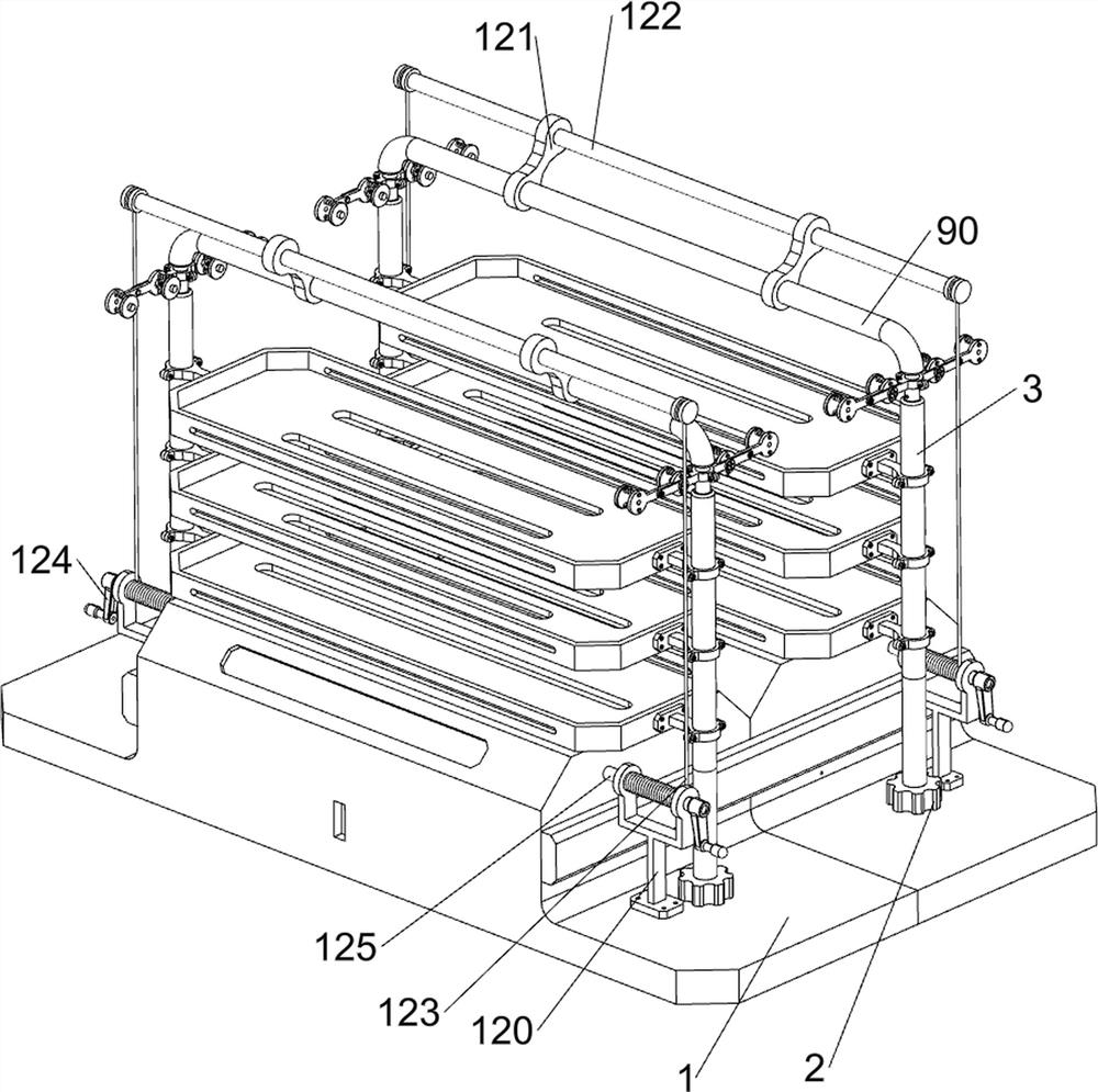
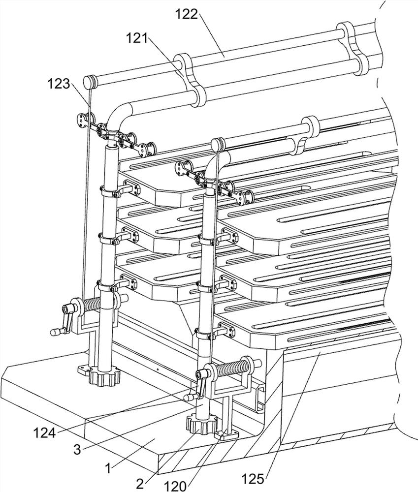
[0084] A needle textile storage rack for textile sales such as Figure 1-Figure 7 As shown, it includes a support frame 1, a fixed block 2, a support rod 3, a first fixed ring 4, a placement plate 5, a slider 6, a limit rail 7, a moving mechanism 8 and a placement mechanism 9, and the number of the support frame 1 is Two, the two supporting frames 1 are in contact, the left and right sides of the top of the two supporting frames 1 are provided with fixed blocks 2, the tops of the four fixed blocks 2 are provided with supporting rods 3, and the upper parts of the four supporting rods 3 are evenly spaced with three The first fixed ring 4 is provided with a placement plate 5 between the two adjacent first fixed rings 4, there are six placement plates 5 for placing textiles, and the left and right sides of the front support frame 1 are provided with limit positions Rail 7, the two limit rails 7 are in contact with the support frame 1 on the rear side, and the left and right sides ...

Embodiment 2

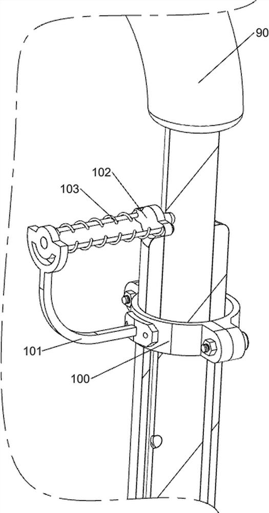
[0089] On the basis of Example 1, such as figure 1 , Figure 8 , Figure 9 and Figure 10 As shown, a lifting mechanism 10 is also included, and the lifting mechanism 10 includes a third fixed ring 100, a fixed frame 101, a block 102, a second return spring 103 and a compression spring 104, and the tops of the four support rods 3 are provided with a third The fixed ring 100, the inner ends of the four third fixed rings 100 are all provided with a fixed frame 101, and the four fixed frames 101 are all slidably provided with a clamping block 102, and the four clamping blocks 102 are tightly matched with the sliding rod 90 on the same side , the left and right sides of the two sliding rods 90 are provided with ten clamping holes, which are used for the clamping blocks 102 to clamp the sliding rods 90, and there are two second clamping holes between the four clamping blocks 102 and the fixed frame 101 on the same side. Two return springs 103, two compression springs 104 are arr...


PUM


Abstract

The invention relates to a storage rack, in particular to a knitwear and textile storage rack for textile sales. According to the knitwear and textile storage rack for textile sales, the storage rack can be moved, and use is more convenient. A knitwear and textile storage rack for textile sales comprises two supporting frames which are in contact with each other; the fixing blocks are arranged on the left sides and the right sides of the tops of the two supporting frames; the supporting rods are arranged at the tops of the four fixing blocks; and three first fixing rings are uniformly arranged at the upper parts of the four supporting rods at intervals. People push the supporting frame to move on the ground through the universal wheels, so that the storage rack is moved to the position where the storage rack needs to be used, people press the brake valve and control the universal wheels to move, the universal wheels stop rotating, and therefore the storage rack can be moved, and use is more convenient.

Description

technical field [0001] The invention relates to a storage rack, in particular to a textile storage rack for textile sales needles. Background technique [0002] Textiles are products made of textile fibers through processing and weaving. After textiles are processed and manufactured, textiles are generally sold. Most of the current sales storage racks are a horizontal bar. People hang textiles on the horizontal bar. Therefore, the amount of textiles that can be displayed is small. [0003] Patent application CN213414608U, with a publication date of 20210611, discloses a textile storage rack, including a storage rack body, the top and bottom of the inner wall of the storage rack body are respectively rotatably connected with a first rotating gear set and a second rotating gear set. A drive motor is fixedly connected to the bottom of one side of the storage rack body, the drive shaft of the drive motor runs through the storage rack body and is fixedly connected to the second ...

Claims


Application Information

Patent Timeline
Patent Type & Authority Applications(China)
IPC IPC(8): A47F7/16A47F5/10A47B91/06
Inventor 李秀英
Owner 深圳市雅奥家纺有限公司
Why Eureka
Try Eureka