Automatic feeding device, machine tool and machine tool machining method
An automatic feeding and machine tool technology, which is applied in metal processing and other fields, can solve problems such as inability to carry out stable feeding, affect work efficiency, and waste labor costs, and achieve the effects of saving manpower consumption, small energy consumption, and reducing work burden
- Summary
- Abstract
- Description
- Claims
- Application Information
AI Technical Summary
Problems solved by technology
Method used
Image
Examples
Embodiment 1
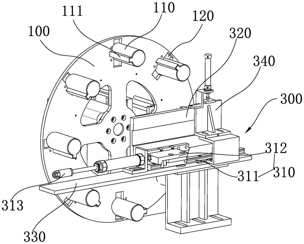
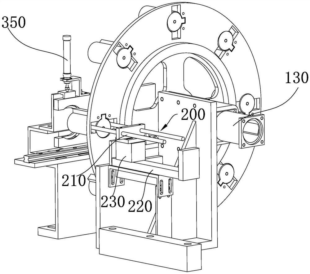
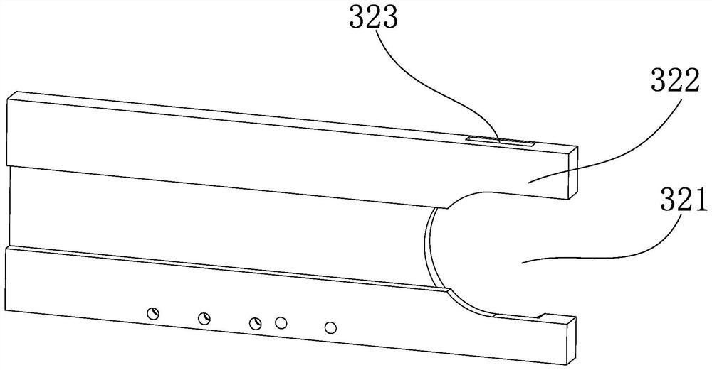
[0043] Such as Figure 1 to 3 As shown, the present invention provides an automatic upper device comprising: a sheet disk 100 having a plurality of material column 110 for the ferrite, and the material column 110 and the place The connection of the upper material disk 100 is provided with a through hole 120; the push mechanism 200, the push mechanism 200 is disposed in the upper orientation direction, and the push mechanism 200 includes a pusher 210 through the push rod. 210 moves the material block 500 on the sheet 110 in the through hole 120 to introduce the material column 110; the jacket mechanism 300, the jacket mechanism 300 is disposed at the discharge opening of the material column 110, The jacket mechanism 300 includes a connected rail 310 and a clamp block 320, wherein the clamping block 320 is introduced to the pushed rod 210 in the rails 310 to introduce the material block 500 of the material column 110 to the machine tool. Processing the spindle 410.
[0044] Further pre...
Embodiment 2
[0060] Such as Figure 4 to 7 As shown, the present invention also provides a machine tool, including a body 400, an automatic charge device according to an embodiment of the body 400, and a machining spindle 410 is provided on the body 400, by which The jacket mechanism 300 delivers the material block 500 on the material column 110 to the machining spindle 410.
[0061] Further preferably, the jaw 411 and the bulletin 412 are provided with a jaw 411 and a bomb sleeve 412 on the crimping surface of the material block 500, and when the fifth cylinder 420 is pressed against the clamp 411. The bubble 412 is in a press-fit state.
[0062] Further preferably, the jaw 411 is three-point jaw 411, and the jaw 411 can be moved in a axial direction near or away from the machining spindle 410.
[0063] Further preferably, such as Figure 8 The display block 500 is a material block 500 applied in the present embodiment.
[0064] In the present embodiment, the automatic upper device is mounted o...
Embodiment 3
[0066] The present invention also provides a machine tool processing method, including steps:
[0067] S1: Pass the material to be processed in accordance with the card position on all the columns;
[0068] S2: When the initial state, the clamping block corresponds to a sheet column, and push the material block on the corresponding material to the clamping block by the second cylinder with the throttle rod.
[0069] S3: Turn the material block in the clamping port by a third cylinder.
[0070] S4: Conveyed by the first cylinder control clamping block to convey the massage spindle along the rail;
[0071]S5: The jaw moves in the axial direction away from the machining spindle, and passes the push block with the jaw in the jaw, and the material block is fixed, the fifth cylinder retraction is fixed.
[0072] S6: Processing blocks by an external tool;
[0073] S7: After the processing is completed, the jaw retraction, the material after processing is bombed under the elastic force of...
PUM
 Abstract
Description
Claims
Application Information
 - R&D
- Intellectual Property
- Life Sciences
- Materials
- Tech Scout
- Unparalleled Data Quality
- Higher Quality Content
- 60% Fewer Hallucinations
Browse by: Latest US Patents, China's latest patents, Technical Efficacy Thesaurus, Application Domain, Technology Topic, Popular Technical Reports.
© 2025 PatSnap. All rights reserved.Legal|Privacy policy|Modern Slavery Act Transparency Statement|Sitemap|About US| Contact US: help@patsnap.com


