Method for operating spinning machine and spinning machine

A spinning machine and yarn technology, applied in the field of operating spinning machines, can solve problems such as excess yarn and slippage

Pending Publication Date: 2022-04-15
SAURER SPINNING SOLUTIONS GMBH & CO KG
View PDF6 Cites 0 Cited by
  • Summary
  • Abstract
  • Description
  • Claims
  • Application Information

AI Technical Summary

Problems solved by technology

[0019] But because the yarn unwinding speed is higher than the yarn winding speed when the yarn is wound onto the winding bobbin during the winding reserve yarn which is well known to form parallel yarn loops at this time, so there is a surplus of yarn, As a result, without special measures such as the use of a yarn brake to communicate with the yarn storage, the resulting yarn reserve is wound loosely so that it may slip out during the subsequent delivery of the cross-wound bobbins

Method used


Image

  • Method for operating spinning machine and spinning machine
  • Method for operating spinning machine and spinning machine
  • Method for operating spinning machine and spinning machine

Examples


Embodiment Construction

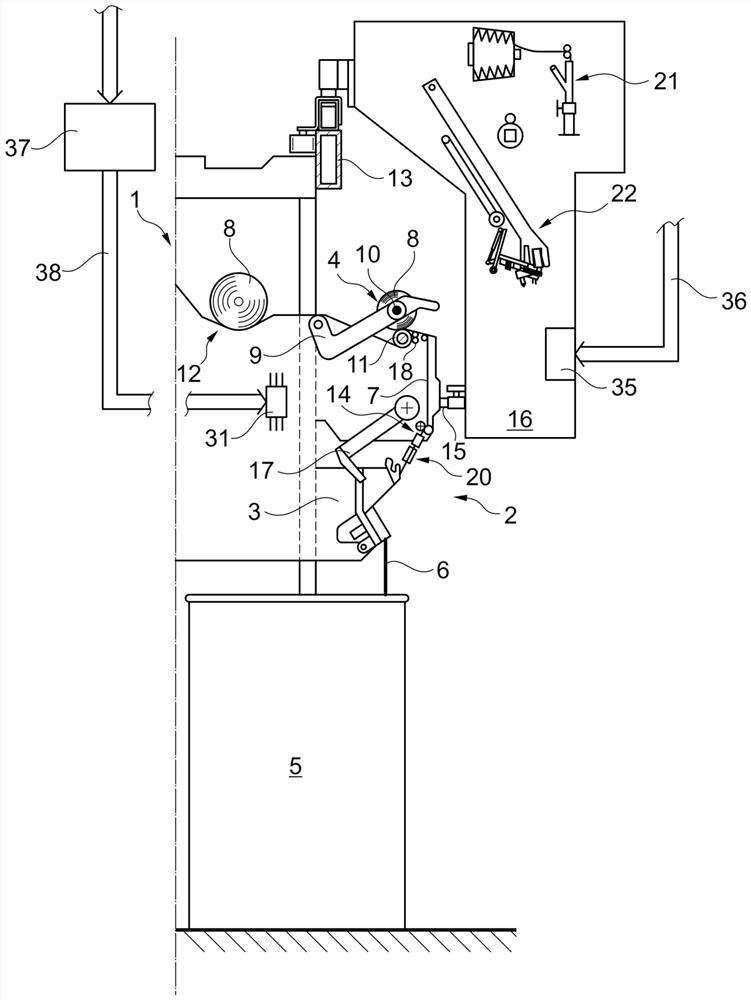
[0093] exist figure 1 shows in side view one half of an open-end rotor spinning machine 1 with a plurality of essentially self-contained workstations 2 . This essentially self-sufficient workstation 2 is equipped with an open-end spinning device 3 and a winding device 4 as usual, wherein the fiber sliver 6 fed in the spinning can 5 is spun in the spinning device 3. A yarn 7 is formed, which is then wound into a cross-wound bobbin 8 on a winding device 4 .

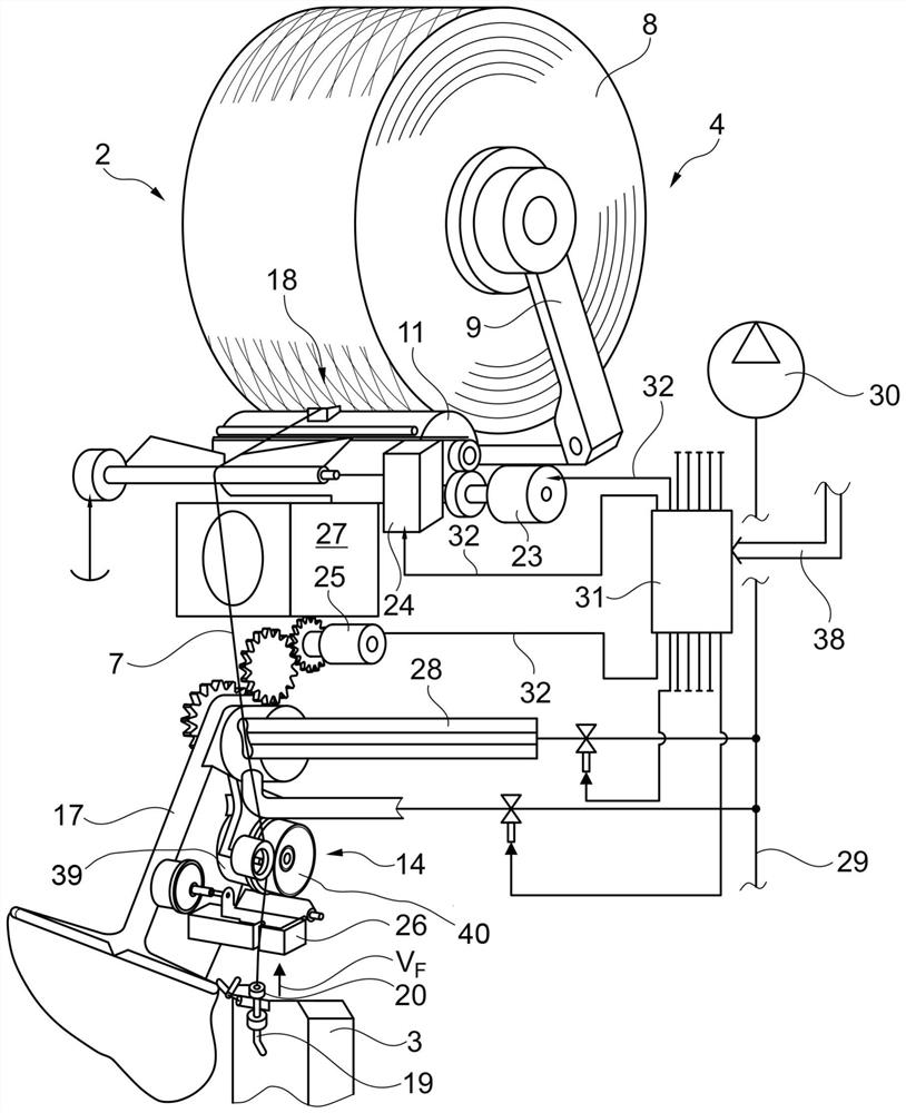
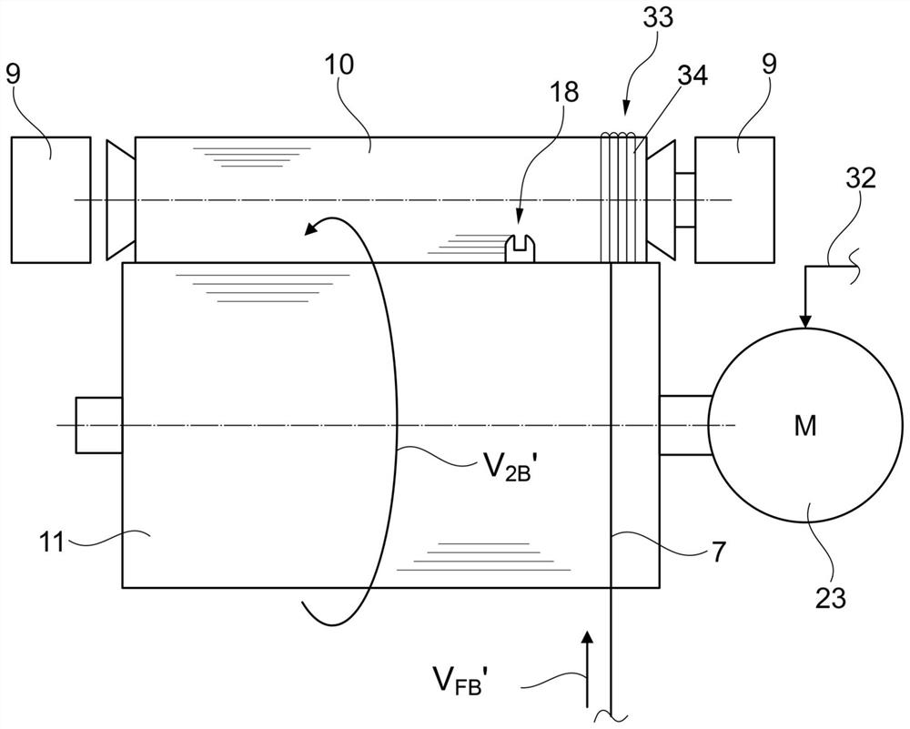
[0094] As shown in the figure, the winding device 4 is equipped for this purpose with a creel 9 for rotatably holding the winding bobbin 10 of the cross-winding bobbin 8 and a separate motor drive for the desired rotation of the winding bobbin 10 or bobbin drive drum 11 for cross-winding bobbins 8 .

[0095] This station 2, which is relatively clearly described, for example in DE 10139075 A1, also has a separately motor-driven yarn traversing device 18, a separately motor-driven yarn unwinding device 14 and a pivotally mo...


PUM


Abstract

The invention relates to a method for operating a spinning machine and a spinning machine. The spinning machine is provided with a plurality of stations, and each station is provided with a spinning device for producing yarns, a yarn unwinding device for unwinding the yarns from the spinning device and a winding device for winding cross-wound bobbins. The winding device is provided with a bobbin creel which is rotatably installed and used for holding a winding bobbin and a drivable bobbin driving roller used for rotating the winding bobbin or cross-winding bobbins, the yarn unwinding device is provided with a drivable unwinding roller, and the station is provided with at least one independent driving device for driving the bobbin driving roller or the unwinding roller. In order to minimize the cost required for the formation of a prescribed reserve yarn in such a spinning machine, the individual drive is controlled during the formation of the reserve yarn in which the yarn is wound in the form of parallel yarn loops onto a winding bobbin, therefore, the winding speed of the yarn and the unwinding speed of the yarn are coordinated and matched with each other, and the generated yarn tension allows the yarn to be reliably fixed and stored on the winding bobbin.

Description

technical field [0001] The invention relates to a method for operating a spinning machine, in particular an open-end rotor spinning machine, which is equipped with a number of stations, each station having a spinning device for the production of yarn, in particular an open-end rotor A spinning device, a yarn unwinding device for unwinding yarn from the spinning device and a winding device for winding a cross-wound bobbin, wherein the winding device has a pivotally mounted Creel for winding bobbins and drivable bobbin drive drum for rotating winding bobbins or cross-winding bobbins, wherein the yarn unwinding device is provided with drivable unwinding rollers and wherein the station is provided with at least one individually driven Device that drives the bobbin drive drum or unwind roll. Background technique [0002] With regard to open-end rotor spinning machines, it has been disclosed and for example shown and explained in DE 19836065 A1 that such a textile machine general...

Claims


Application Information

Patent Timeline
Patent Type & Authority Applications(China)
IPC IPC(8): B65H59/38B65H54/46B65H54/74B65H54/06B65H63/08D01H4/08
CPCB65H54/343B65H59/385B65H59/388B65H2701/31
Inventor 保罗·施特拉藤
Owner SAURER SPINNING SOLUTIONS GMBH & CO KG
Why Eureka
Try Eureka