Energy-saving spherical friction rotating speed adjusting type winding equipment for two-for-one twisting yarn production
A technology for adjusting speed and winding equipment, which is applied to continuous winding spinning machines, textiles and papermaking, spinning machines, etc., to achieve the effect of improving practicability and reducing energy consumption
- Summary
- Abstract
- Description
- Claims
- Application Information
AI Technical Summary
Problems solved by technology
Method used
Image
Examples
Embodiment 1
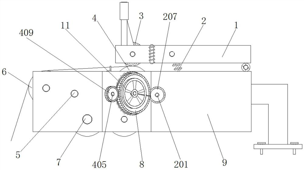
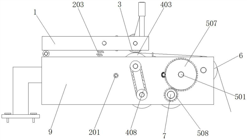
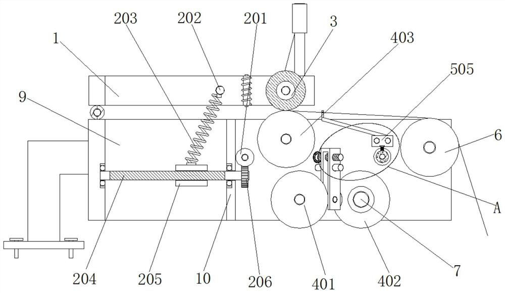
[0040] Example 1, such as Figure 1-6 As shown in and 8-9, when the thicker yarn needs to be wound, the operator manually rotates the driving gear 8 clockwise through the hand wheel 11, and the driving gear 8 cooperates with the second gear 409 to drive the first threaded rod 405 to reverse The hour hand rotates, and the U-shaped movable frame 406 is forced to move to the end away from the driving gear 8 with the driving ball 407 by using the screw thread effect. The diameter of the driven tapered roller 401 contacted by 407 gradually increases, and the transmission between the driven tapered roller 401 and the driving tapered roller 402 changes, so that the rotating speed of the driven tapered roller 401 decreases, and through The rotating speed of the transmission guide roller 403, which is transmission-connected to the driven tapered roller 401 by the transmission device 408, also decreases gradually. The thicker yarn is wound up, at the same time, the clockwise driving ge...
Embodiment 2
[0041] Example 2, such as Figure 1-6 As shown in and 8-9, when the thinner yarn needs to be wound, the operator manually rotates the driving gear 8 counterclockwise through the hand wheel 11, and the driving gear 8 cooperates with the second gear 409 to drive the first threaded rod 405 The hour hand rotates, and the U-shaped movable frame 406 is forced to move to the end close to the driving gear 8 with the driving ball 407 by using the thread effect. The diameter of the driven tapered roller 401 contacted by 407 gradually becomes smaller. During the process, the transmission between the driven tapered roller 401 and the driving tapered roller 402 is constantly changing, so that the rotating speed of the driven tapered roller 401 is accelerated, and through the transmission The rotation speed of the transmission guide roller 403 that is connected to the driven tapered roller 401 by the device 408 is also gradually accelerated. Correspondingly, the rotation of the winding roll...
Embodiment 3
[0042] Example 3, such as Figure 1-4 As shown in 7-9, when the drive shaft 7 drives the winding roller 3 to rotate the coil through the speed regulating assembly 4, the transmission of the large gear 507 and the pinion 508 is used to drive the rotating roller 501 to rotate, and when the rotating roller 501 rotates, Due to the cooperation of the guide ring 502 and the rolling wheel 503, the movable block 505 is forced to swing back and forth on the outside of the second slide bar 504, which drives the guide bar 506 to swing back and forth, so that the yarn passing through the guide hole on the guide bar 506 can be evenly Winding to the outside of the winding roller 3 does not require other external drive structures, thereby reducing the energy consumption of the two-for-one twister using the winding device during work, and making the winding device more energy-efficient.
[0043] Working principle: connect the power to the device before use, first pass the twisted yarn end thr...
PUM
 Abstract
Description
Claims
Application Information
 - R&D
- Intellectual Property
- Life Sciences
- Materials
- Tech Scout
- Unparalleled Data Quality
- Higher Quality Content
- 60% Fewer Hallucinations
Browse by: Latest US Patents, China's latest patents, Technical Efficacy Thesaurus, Application Domain, Technology Topic, Popular Technical Reports.
© 2025 PatSnap. All rights reserved.Legal|Privacy policy|Modern Slavery Act Transparency Statement|Sitemap|About US| Contact US: help@patsnap.com


