Locating piece for speed reducer of computerized embroidery machine

A deceleration device, embroidery machine technology, applied in the direction of embroidery machines, auxiliary devices, embroidery machine mechanisms, etc., can solve the problems of deceleration device without positioning parts, poor equipment operation stability, loose connection parts, etc., to prevent misalignment and improve tightness Solidity, the effect of improving stability

Pending Publication Date: 2022-04-15
孟建玲
View PDF6 Cites 0 Cited by
  • Summary
  • Abstract
  • Description
  • Claims
  • Application Information

AI Technical Summary

Problems solved by technology

[0003] During the use of the computerized embroidery machine, it is inevitable to use a deceleration device. The stability of the deceleration device determines the operation status of the entire equipment. However, the deceleration device of the existing computerized embroidery machine does not have corresponding positioning parts. After a long time of use, All connecting parts are loose, and the stability of equipment operation is poor, which ultimately affects product quality

Method used


Image

  • Locating piece for speed reducer of computerized embroidery machine
  • Locating piece for speed reducer of computerized embroidery machine
  • Locating piece for speed reducer of computerized embroidery machine

Examples


Embodiment Construction

[0026] The following will clearly and completely describe the technical solutions in the embodiments of the present invention with reference to the accompanying drawings in the embodiments of the present invention. Obviously, the described embodiments are only some, not all, embodiments of the present invention. Based on the embodiments of the present invention, all other embodiments obtained by persons of ordinary skill in the art without making creative efforts belong to the protection scope of the present invention.

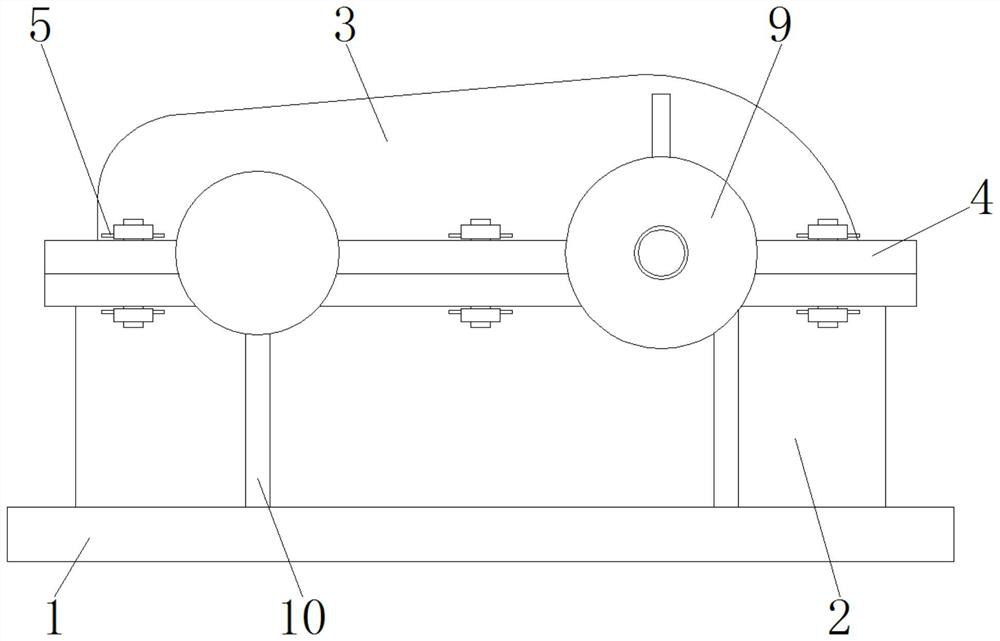
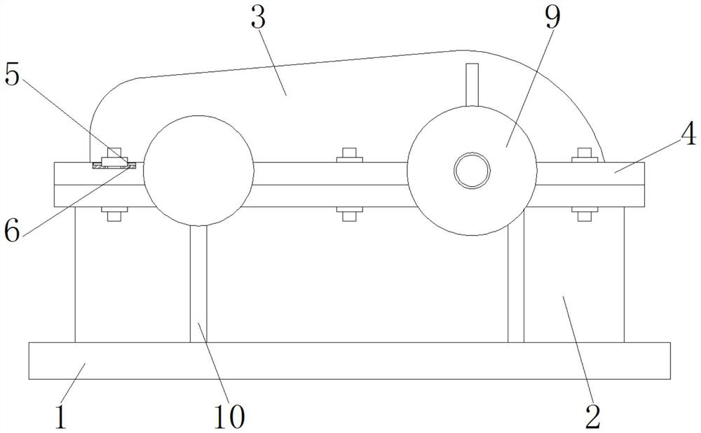
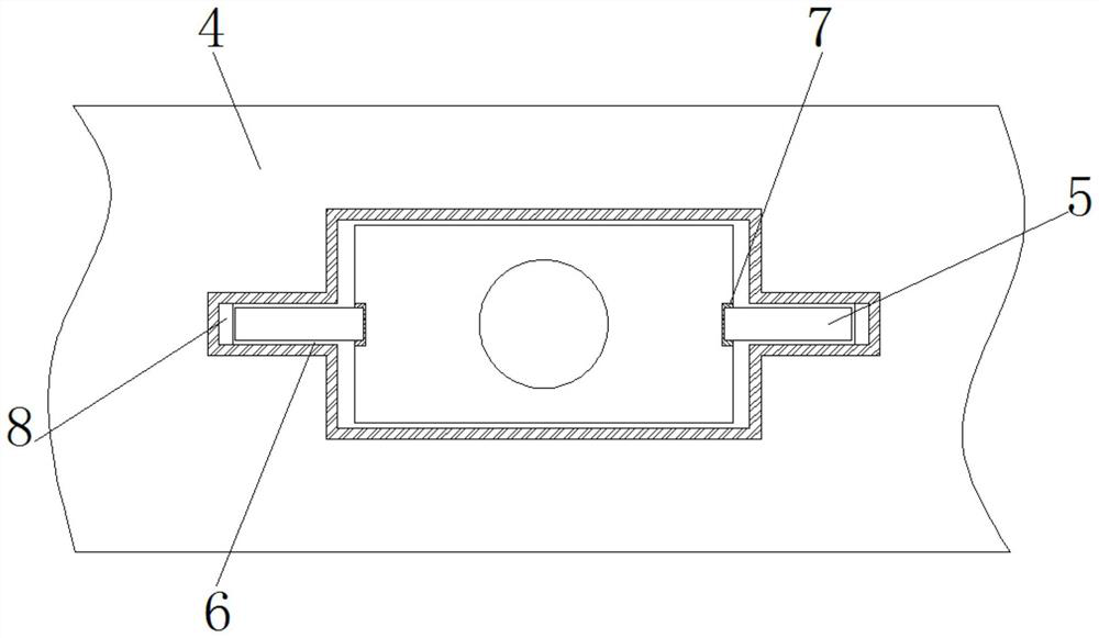
[0027] see figure 1 , a computer embroidery machine deceleration device positioner, including a base 1, the top surface of the base 1 is fixedly installed with a connecting seat 2, the top of the connecting seat 2 is provided with a box cover 3, the top surface of the connecting seat 2 and the bottom surface of the box cover 3 Both are fixedly installed with a mounting plate 4, and the two mounting plates 4 are fixedly connected by nuts and bolts, and a positi...


PUM


Abstract

The invention discloses a positioning piece for a speed reducing device of a computerized embroidery machine, relates to the technical field of positioning of speed reducing mechanisms, and aims to provide the positioning piece for the speed reducing device of the computerized embroidery machine, which can prevent a nut from rotating reversely, avoid dislocation of all parts and enhance the running stability of equipment. A box cover is arranged above the connecting seat, mounting plates are fixedly mounted on the top surface of the connecting seat and the bottom surface of the box cover, the two mounting plates are fixedly connected through nuts and bolts, and positioning parts are detachably connected between the nuts and the mounting plates. The nut is prevented from rotating reversely during equipment operation, the fastening performance of the device is improved, dislocation of all parts is prevented, stable equipment operation is ensured, meanwhile, the positioning part is detachably arranged, workers can conveniently disassemble the equipment to overhaul internal parts, the structure is simple, and operability is high.

Description

technical field [0001] The invention relates to the technical field of positioning of a deceleration mechanism, in particular to a positioning part of a deceleration device of a computerized embroidery machine. Background technique [0002] Computerized embroidery machine is the most advanced embroidery machine in the contemporary era. It can achieve high-speed and high-efficiency traditional hand-embroidered embroidery, and can also meet the multi-level, multi-functional, uniform and perfect requirements that cannot be achieved by hand-embroidered embroidery. It is an electromechanical product that embodies a variety of high-tech. [0003] During the use of the computerized embroidery machine, it is inevitable to use a deceleration device. The stability of the deceleration device determines the operation status of the entire equipment. However, the deceleration device of the existing computerized embroidery machine does not have corresponding positioning parts. After a long...

Claims


Application Information

Patent Timeline
Patent Type & Authority Applications(China)
IPC IPC(8): D05C5/00D05C13/00
Inventor 孟建玲
Owner 孟建玲
Why Eureka
Try Eureka