Panel pillar advanced pressure relief subsequent filling mining method

A mining method and ore pillar technology, which can be used in filling, ground mining, mining equipment, etc., can solve problems such as low work efficiency and poor safety.

Pending Publication Date: 2022-04-15
CHINA ENFI ENGINEERING CORPORATION
View PDF0 Cites 0 Cited by
  • Summary
  • Abstract
  • Description
  • Claims
  • Application Information

AI Technical Summary

Problems solved by technology

The safety of the above methods is poor and the work efficiency is low, so the

Method used


Image

  • Panel pillar advanced pressure relief subsequent filling mining method
  • Panel pillar advanced pressure relief subsequent filling mining method
  • Panel pillar advanced pressure relief subsequent filling mining method

Examples


Embodiment 1

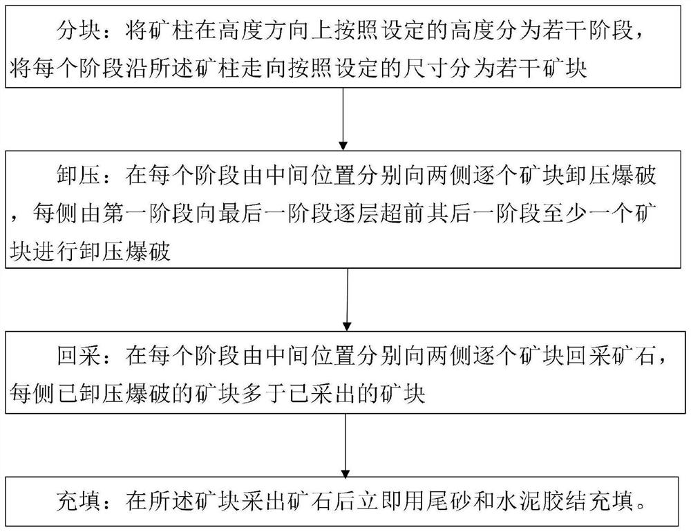
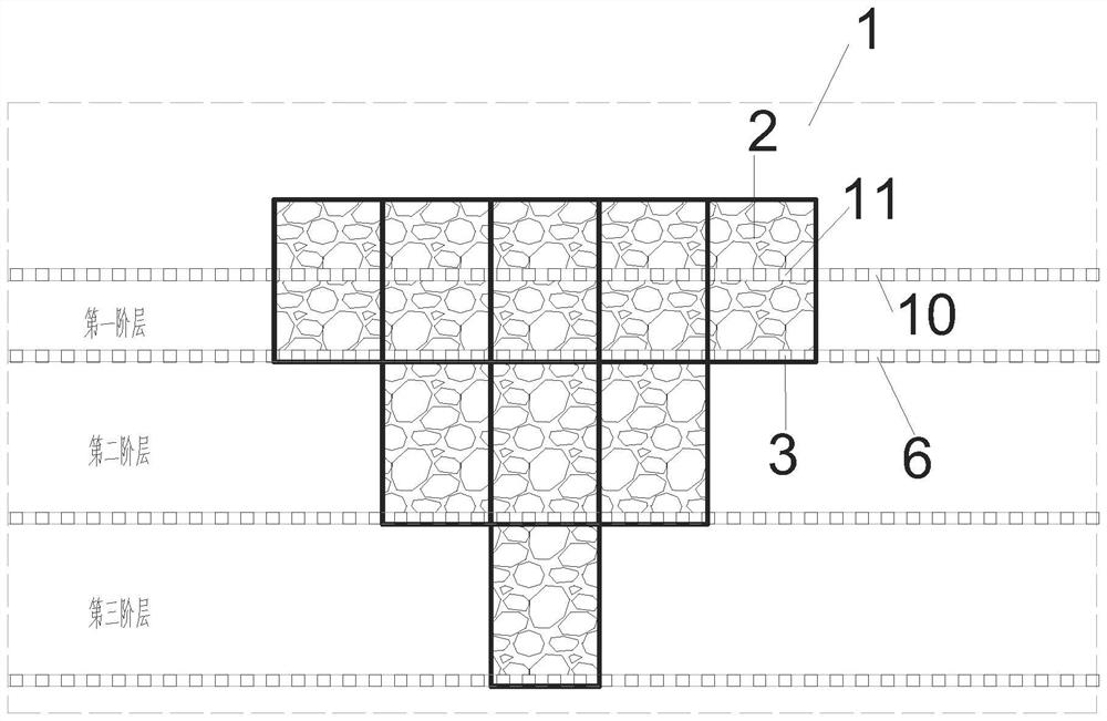
[0031] figure 1 It is a flow chart of the mining method for panel pillars in advance of depressurization and subsequent filling according to Embodiment 1 of the present invention, figure 2 It is a structural schematic diagram of the pressure relief in advance from the top of the ore pillar according to Embodiment 1 of the present invention.

[0032] like figure 1 and figure 2 It can be seen that the mining method for panel pillars proposed in this embodiment is to relieve pressure in advance and then fill, which can be used for safe recovery of panel pillars in extra-large deep wells. Panel pillars refer to the ore pillars left to support the panel roof and ensure the safety and stability of the stope structure during the large-scale mining of thick and large ore bodies, generally in the form of cuboids. In open-pit mining, the stope is usually divided into mine rooms and ore pillars, and the ore pillars are recovered after mining in the mine rooms. During the recovery p...

Embodiment 2

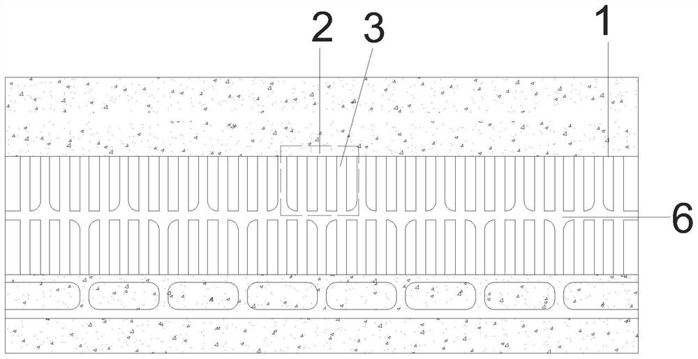
[0062] Figure 8 It is a structural schematic diagram of an advanced pressure relief from the bottom of the pillar according to Embodiment 2 of the present invention.

[0063] like Figure 8 As shown, the panel mining method provided by this embodiment is based on the first embodiment, and starts from the bottom of the pillar to relieve the pressure and then fill. The first stage can be the bottom of the pillar. stage, the last stage is the uppermost stage of the ore pillar. From the bottom to the top, it is divided into the first stage, the second stage, the third stage, etc., and the construction starts from the first stage layer by layer. The ore blocks blasted on each side of the first stage are at least one ahead of the ore blocks blasted on each side of the second stage, and the ore blocks blasted on each side of the second stage are higher than the ore blocks blasted on each side of the third stage At least one ahead, and so on, the ore blocks that have been depressu...


PUM

PropertyMeasurementUnit
Depthaaaaaaaaaa

Abstract

The invention provides a panel ore pillar advanced pressure relief subsequent filling mining method which comprises the following steps: partitioning: partitioning an ore pillar into a plurality of stages according to a set height in the height direction, and partitioning each stage into a plurality of ore blocks according to a set size along the trend of the ore pillar; pressure relief is conducted, specifically, pressure relief blasting is conducted on ore blocks one by one from the middle position to the two sides in each stage, and pressure relief blasting is conducted on at least one ore block ahead of the next stage layer by layer from the first stage to the last stage on each side; stoping: stoping ore from the middle position to the two sides one by one in each stage, wherein the ore blocks subjected to pressure relief blasting on each side are more than the stoped ore blocks; and filling: after ore is extracted from the ore blocks, tailings and cement are immediately used for cemented filling. By means of the method, pressure relief blasting is conducted layer by layer before the next layer, and safe and efficient ore pillar recycling is achieved.

Description

technical field [0001] The invention relates to the technical field of mining, and more specifically, relates to a mining method for a panel ore pillar with pressure relief in advance and subsequent filling. Background technique [0002] With the gradual depletion of shallow resources, large-scale deep well mining is gradually increasing. Due to the technical problems of high ground stress in deep well mining, for large-scale deep mining of thick and large ore bodies, usually after the mining house is recovered, the panel pillars are left behind Support the goaf. And according to the calculation of rock mechanics, considering the safety of mining operations and the stability of the tunnel engineering in the pillar, the size of the pillars in the panel area is often large. If the pillars are left behind, the loss of resources will be large. [0003] At present, there are many studies on the safe recovery of ore pillars in deep well panels, but they are generally limited to c...

Claims


Application Information

Patent Timeline
IPC IPC(8): E21C41/22E21F15/00
CPCE21C41/22E21F15/00
Inventor 刘育明张爱民张少杰李文吴昊燕
Owner CHINA ENFI ENGINEERING CORPORATION
Why Eureka
Try Eureka