Cam connecting rod mechanism

A cam link and lever technology, applied in mechanical equipment, belts/chains/gears, transmissions, etc., can solve the problems of lack, low accuracy of round holes, and insufficient practicability.

Pending Publication Date: 2022-04-15
昆山美琳泽电子科技有限公司
View PDF1 Cites 1 Cited by
  • Summary
  • Abstract
  • Description
  • Claims
  • Application Information

AI Technical Summary

Problems solved by technology

[0004] 1. Patent document CN210148833U discloses a punching device, including "a clamping assembly for clamping and positioning a workpiece and a punching assembly for punching a hole in a workpiece. The punching assembly is slidably mounted on the clamping assembly, and the clamping assembly There is a through hole, the punching component is coaxial with the through hole, the paper bag is fixed and clamped by the clamping component, and the paper bag is punched by the punching device, the structure is simple, the punching efficiency is high, and it is convenient for subsequent automation equipment to process The paper bag after the punching device is threaded." The above-mentioned device lacks a cam link structure, which leads to low accuracy of the round holes punched by the device, which leads to poor use of the device and poor practicability. insufficient

Method used


Image

  • Cam connecting rod mechanism
  • Cam connecting rod mechanism
  • Cam connecting rod mechanism

Examples


Embodiment 1

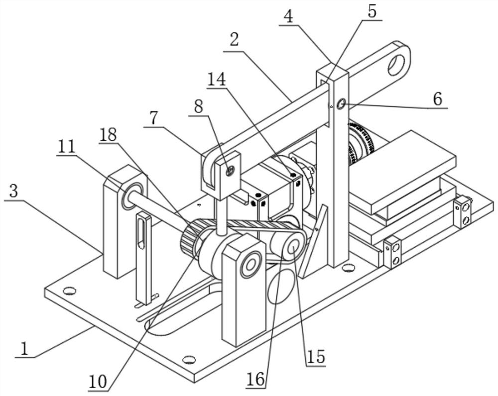
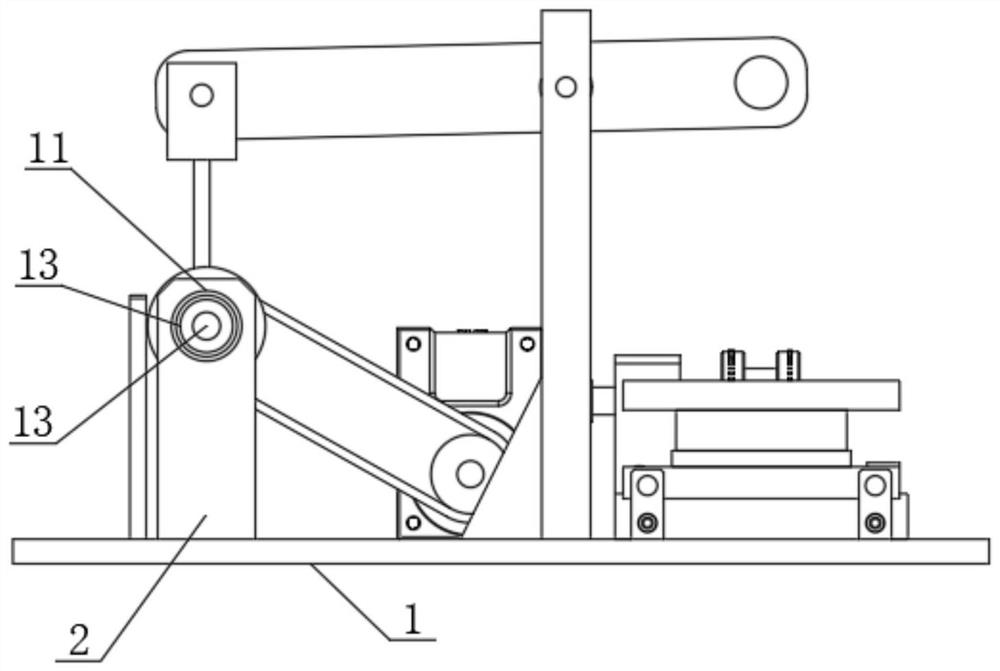
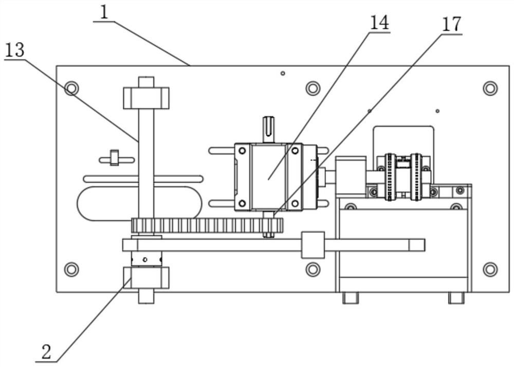
[0026] see figure 1 , figure 2 , image 3 with Figure 4 , an embodiment provided by the present invention, a cam linkage mechanism, including a base plate 1, a lever 2 and a fixed plate 3, a lever 2 is arranged above the base plate 1, and a fixed plate 3 is installed on both sides of the top front end of the base plate 1 A support rod 4 is installed on one side of the top of the base plate 1, a square hole 5 is provided on the top of the front of the support rod 4, and the tail end of the lever 2 is inserted into the inside of the square hole 5, and one side of the inner wall of the square hole 5 is connected with a second A rotating shaft 6, and the tail end of the first rotating shaft 6 runs through one side of the lever 2 and is connected to the other side of the inner wall of the square hole 5, the front end of the lever 2 is sleeved with a U-shaped clip 7, and one side of the inner wall of the U-shaped clip 7 is connected There is a second rotating shaft 8, and the t...


PUM


Abstract

The cam connecting rod mechanism comprises a bottom plate, a lever and fixing plates, the lever is arranged above the bottom plate, the fixing plates are installed on the two sides of the front end of the top of the bottom plate, a supporting rod is installed on one side of the top of the bottom plate, and a square hole is formed in the top of the front face of the supporting rod; and the tail end of the lever is inserted into the square hole, and one side of the inner wall of the square hole is connected with a first rotating shaft. Through matched use of the bottom plate, a lever, a fixing plate, a supporting rod, a square hole, a first rotating shaft, a U-shaped clamp, a second rotating shaft, a connecting rod, a connecting ring, a cylindrical hole, a bearing, a third rotating shaft, a motor base, a driving shaft, a first carrier roller, a crawler belt, a second carrier roller and a cam, through the principle that the lever is triggered through rotation of an eccentric shaft, when the device is used for punching an object, the punching efficiency is improved; and the punched holes are more accurate, so that the high efficiency of the device is reflected, and the practicability of the device is reflected.

Description

technical field [0001] The invention relates to the technical field of drilling, in particular to a cam linkage mechanism. Background technique [0002] The cam link mechanism mainly uses the principle of an eccentric shaft to rotate and touch the lever, and the object is punched through the lever principle. Compared with the existing punching device, the round hole punched by the cam link mechanism is more precise. [0003] A kind of shortcoming of cam linkage mechanism in the prior art is insufficient: [0004] 1. The patent document CN210148833U discloses a punching device, including "a clamping assembly for clamping and positioning a workpiece and a punching assembly for punching a hole in the workpiece. The punching assembly is slidably mounted on the clamping assembly, and on the clamping assembly There is a through hole, the punching component is coaxial with the through hole, the paper bag is fixed and clamped by the clamping component, and then the paper bag is pun...

Claims


Application Information

Patent Timeline
Patent Type & Authority Applications(China)
IPC IPC(8): F16H37/12
Inventor 王青
Owner 昆山美琳泽电子科技有限公司
Why Eureka
Try Eureka