Portable and transported gate device matched with multiple access control devices for use

A gate, access control technology, applied in the direction of a single input/output port register, instrument, time register, etc., can solve the problems of increasing capital expenditure, inability to carry it arbitrarily, increasing work intensity, etc., to avoid adjustment. cumbersome effect

Inactive Publication Date: 2022-04-15
唐伟峰
View PDF0 Cites 1 Cited by
  • Summary
  • Abstract
  • Description
  • Claims
  • Application Information

AI Technical Summary

Problems solved by technology

[0003] In order to solve the above technical problems, a gate device that is used in combination with various access control devices for portable transportation is provided. The access control is different types of access control equipment, so the entire gate needs to be replaced, and the access control equipment cannot be replaced quickly and independently, resulting in the need to re-purchase the entire access control gate with different types, and increase capital expenditure, and most of the existing access control gates are fixed in the On the ground, when changing the site, it usually needs to be cumbersomely disassembled or discarded. It is impossible to directly fold the access control gate into a box to reduce the occupation of transportation space, and it cannot be carried arbitrarily for transportation, which leads to a certain limitation in the scope of use and requires manual disassembly to replace the site. The problem of increased work intensity

Method used


Image

  • Portable and transported gate device matched with multiple access control devices for use
  • Portable and transported gate device matched with multiple access control devices for use
  • Portable and transported gate device matched with multiple access control devices for use

Examples


Embodiment 1

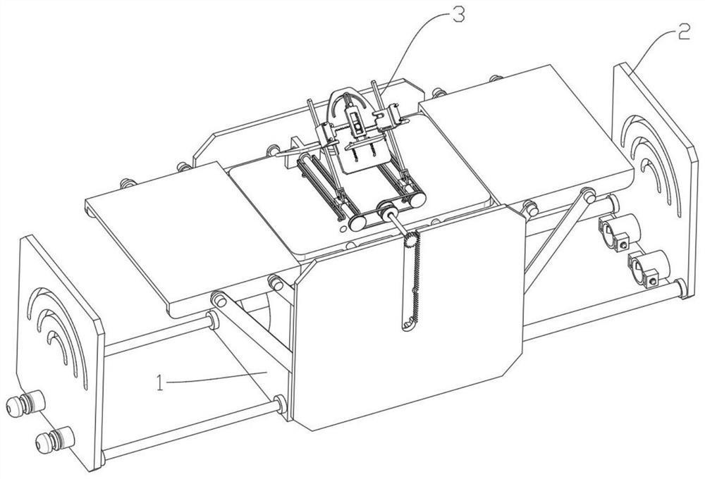
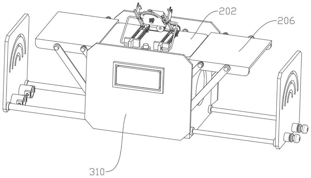
[0029] Please refer to Figure 1 to Figure 7 box Figure 9As shown, a gate device used in combination with various access control equipment for portable transportation, including a box body 1, the inner upper end of the box body 1 is provided with a splicing lift-out gate mechanism 2, and the upper end of the splicing lift-out gate mechanism 2 is provided with an angle adjustment for arbitrary replacement Mechanism 3, splicing and lifting the gate mechanism 2 includes a spring thread rod 201, an internal thread lifting plate 202, a main force rod 203, and twin semicircular gears 204. The upper end of the spring thread rod 201 is threaded with an internal thread lifting plate 202, and the internal thread lifting plate 202 Both ends are rotatably connected with a main force rod 203, and the lower end of the main force rod 203 is rotatably connected with twin semicircular gears 204, and one end of the twin semicircular gears 204 is rotatably connected to the outer surfaces of the...

Embodiment 2

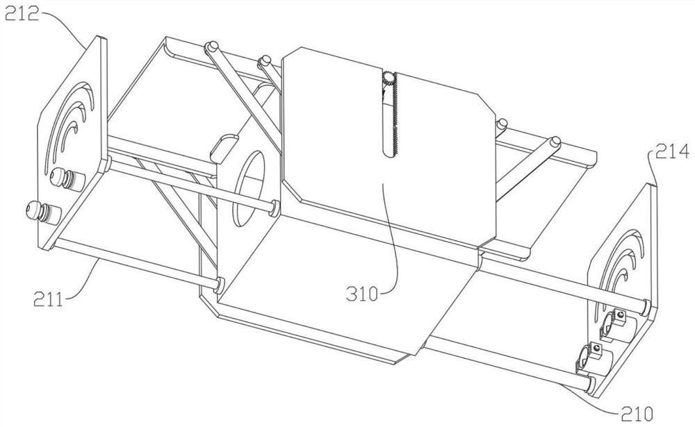
[0033] Please refer to figure 2 and image 3 and Figure 8 and Figure 9 As shown, the angle adjustment arbitrary replacement mechanism 3 includes twin threaded rods 301, square threaded sleeves 302, adjustment frame 303, curved support rods 304, hollow chute plates 305, staggered pulleys 306, twin pulleys 307, power gears 308, single Side sawtooth plate 309, baffle plate 310, internal thread lifting plate 202 upper ends are rotatably connected with twin threaded rods 301, and the right ends of twin threaded rods 301 are threaded with square threaded sleeves 302, and the upper ends of square threaded sleeves 302 are rotatably connected with adjusting frame 303, adjusting frame The left end of 303 is rotatably connected with a curved support rod 304, the left end of the curved support rod 304 is rotatably connected to the left end of the internal thread lifting plate 202, the left and right ends of the square threaded sleeve 302 are slidably connected with a hollow chute pla...

Embodiment 3

[0038] Please refer to Figure 1 to Figure 9 As shown, a gate device used in combination with various access control equipment for portable transportation, including a box body 1, the inner upper end of the box body 1 is provided with a splicing lift-out gate mechanism 2, and the upper end of the splicing lift-out gate mechanism 2 is provided with an angle adjustment for arbitrary replacement Mechanism 3, splicing and lifting the gate mechanism 2 includes a spring thread rod 201, an internal thread lifting plate 202, a main force rod 203, and twin semicircular gears 204. The upper end of the spring thread rod 201 is threaded with an internal thread lifting plate 202, and the internal thread lifting plate 202 Both ends are rotatably connected with a main force rod 203, and the lower end of the main force rod 203 is rotatably connected with twin semicircular gears 204, and one end of the twin semicircular gears 204 is rotatably connected to the outer surfaces of the front and rea...


PUM


Abstract

The invention discloses a portable and transported gate device matched with various access control devices for use, the upper end of a splicing lift-out gate mechanism is provided with an angle adjustment random replacement mechanism, the splicing lift-out gate mechanism comprises a spring threaded rod, an internal thread lifting plate, a main force rod and a double semicircular gear, the upper end of the spring threaded rod is in threaded connection with the internal thread lifting plate, and the upper end of the main force rod is in threaded connection with the double semicircular gear; main force rods are rotationally connected to the front end and the rear end of the internal thread lifting plate correspondingly, double semicircular gears are rotationally connected to the lower ends of the main force rods, one ends of the double semicircular gears are rotationally connected to the outer surfaces of the front end and the rear end of the box body correspondingly, and power rods are fixedly connected to one ends of the double semicircular gears correspondingly. When the gate device is in butt joint, a square plate hollow cylinder and a square plate round head rod are firstly pulled to drive a hollow rod and a thin rod to be pulled out of a box body, then a plurality of gate devices are taken out and aligned, then the gate devices are pushed, the square plate round head rod is driven to be in butt joint with the interior of a square plate hollow cylinder arranged on another gate device, and in the butt joint process, the square plate round head rod extrudes a slope spring rod to move towards the two sides.

Description

technical field [0001] The invention relates to the field of access control, in particular to a gate device used in conjunction with a variety of portable and transportable access control devices. Background technique [0002] When using access control gates on construction sites or temporary places, usually the access control on the gates are different types of access control equipment, and the entire gate needs to be replaced. It is impossible to quickly and independently replace the access control equipment, resulting in the need to re-purchase the entire access control gate with different types , and increased capital expenditure, and most of the existing access control gates are fixed on the ground. When changing the site, it usually needs to be cumbersomely disassembled or discarded. Transportation leads to a certain limitation in the scope of use, and requires manual disassembly and replacement of the site, which increases the work intensity. Contents of the inventi...

Claims


Application Information

Patent Timeline
Patent Type & Authority Applications(China)
IPC IPC(8): G07C9/10
Inventor 唐伟峰
Owner 唐伟峰
Why Eureka
Try Eureka