Cutting equipment for rubber processing

A cutting equipment and rubber technology, applied in the field of rubber processing, can solve the problems of the size deviation of the rubber pad, the positional deviation of the upper rubber sheet and the lower rubber sheet, etc., to achieve the effect of enhancing the grip

Inactive Publication Date: 2020-12-18
徐松
View PDF6 Cites 3 Cited by
  • Summary
  • Abstract
  • Description
  • Claims
  • Application Information

AI Technical Summary

Problems solved by technology

[0003] If the rubber pad cutting machine is cutting two superimposed large rubber sheets synchronously, and the large rubber sheet is nitrile rubber with strong toughness, it is easy for the cutter head to push the rubber sheet towards the end when the rubber sheet is about to break. The direction of being cut is deformed and protruded, so that the moment the rubber sheet is cut off, the position of the upper rubber sheet and the lower rubber sheet will be offset due to the recoil force of the two rubber sheets, so that the subsequent cut rubber sheet Dimensions may vary

Method used


Image

  • Cutting equipment for rubber processing
  • Cutting equipment for rubber processing
  • Cutting equipment for rubber processing

Examples


Embodiment 1

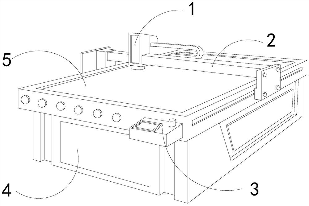
[0026] For example figure 1 -example Figure 5 Shown:

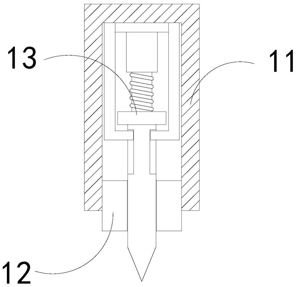
[0027] The invention provides a cutting device for rubber processing, the structure of which includes a cutting mechanism 1, a driving frame 2, a console 3, a base 4, and an operating table 5, and the driving frame 2 is installed at the upper end of the operating table 5, so that The console 3 is embedded and fixed at the front end of the console 5, the base 4 and the console 5 are an integrated structure, the cutting mechanism 1 is movably engaged with the drive frame 2; the cutting mechanism 1 includes an outer frame 11, The lower block 12 and the cutting tool 13 , the lower block 12 is embedded and connected with the lower end of the inner wall of the outer frame 11 , and the cutting tool 13 is movably engaged with the inner part of the outer frame 11 .

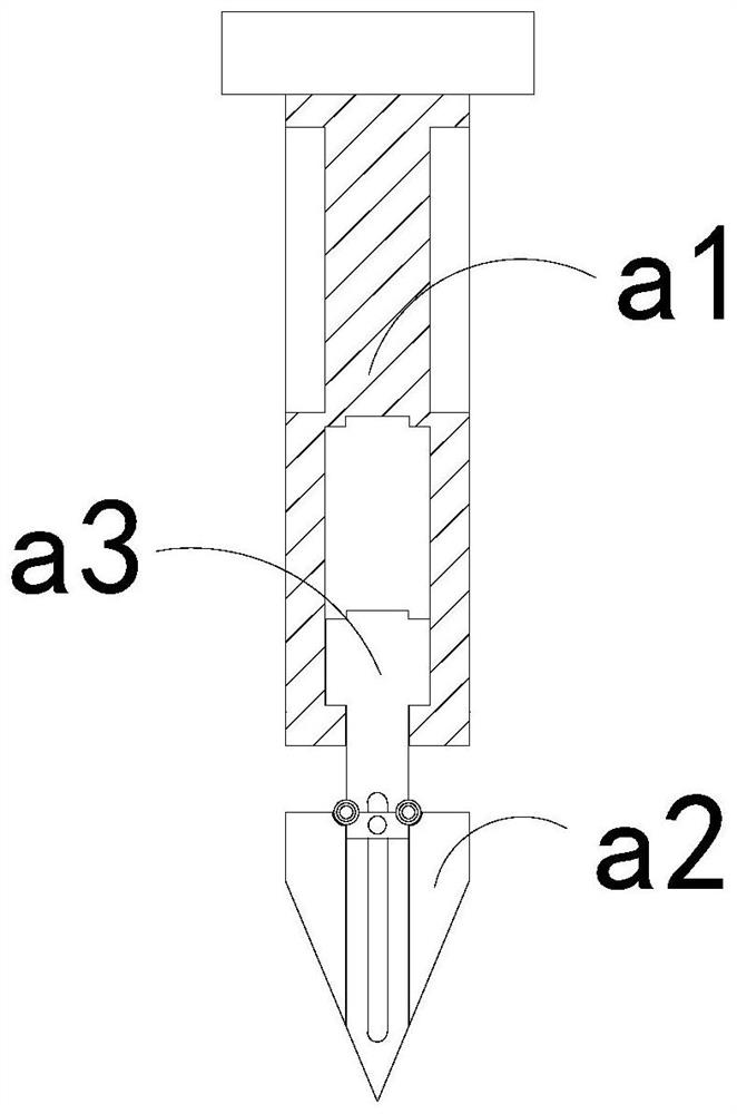
[0028] Wherein, the cutting tool 13 includes a knife bar a1, a fixed frame a2, and a blade a3. The fixed frame a2 is movably engaged with the blade a3, and the blad...

Embodiment 2

[0034] For example Figure 6 -example Figure 8 Shown:

[0035] Wherein, the blade a3 includes a receiving plate c1, a reset piece c2, and an outward expansion plate c3, the reset plate c2 is installed between the outward expansion plate c3 and the receiving plate c1, and the outward expansion plate c3 is hingedly connected to the side of the receiving plate c1 , there are three outer panels c3, which are evenly distributed symmetrically on the left and right sides of the lower end of the receiving panel c1, through the reverse pulling force generated by the cut surface of the rubber sheet on the outer panel c3, the outer panel c3 can be moved along the receiving panel c1 swing down.

[0036] Wherein, the outward expansion board c3 includes a board body c31, an elastic piece c32, a bearing plate c33, and a grip groove c34. c33 is an integrated structure, and the gripping groove c34 has a triangular concave structure, and the frictional force generated by the cut surface of ...


PUM


Abstract

The invention discloses cutting equipment for rubber processing. The cutting equipment structurally comprises a cutting mechanism, a driving frame, a control table, a base and an operation table, wherein the driving frame is arranged at the upper end of the operation table, the control table is fixedly embedded in the front end of the operation table, the base and the operation table are of an integrated structure, and the cutting mechanism is movably clamped with the driving frame. Continuous reverse thrust is generated on a fixed framework through a rubber sheet, an outer swing plate can beunfolded outwards along a middle fixing block, so that a friction increasing surface can downwards extrude the rubber sheet, then the friction force between the rubber sheet and the friction increasing surface can be enhanced through the friction increasing surface, and deviation of the rubber sheet can be avoided when the rubber sheet is cut off; an outer unfolding plate can swing outwards alonga bearing plate to be unfolded through reverse pulling generated by the section of the rubber sheet on the outer unfolding plate, so that the outer unfolding plate can upwards push out a reset sheet;and the grabbing force on the section of the rubber sheet can be enhanced through a grabbing force groove in the outer unfolding plate, so that the fixed framework can be more easily pushed out of therubber sheet.

Description

technical field [0001] The invention relates to the field of rubber processing, in particular to a cutting device for rubber processing. Background technique [0002] The rubber mat cutting machine is mainly used for cutting large pieces of rubber sheet. It can drive the cutting tool to move through the moving frame, so that the cutter head protruding from the bottom of the cutting tool can cut the large piece of rubber sheet on the operating table. , so that it can be cut into small pieces of rubber pads, which are widely used in rubber pad production industries such as mouse pads. Based on the above description, the inventors found that the existing cutting equipment for rubber processing mainly has the following deficiencies, For example: [0003] If the rubber pad cutting machine is cutting two superimposed large rubber sheets synchronously, and the large rubber sheet is nitrile rubber with strong toughness, it is easy for the cutter head to push the rubber sheet toward...

Claims


Application Information

Patent Timeline
Patent Type & Authority Applications(China)
IPC IPC(8): B26D7/02B26D7/08B26D7/26B26D3/00
CPCB26D3/003B26D7/02B26D7/088B26D7/2614
Inventor 徐松
Owner 徐松
Why Eureka
Try Eureka