Lighting control circuit and chip
A lighting control circuit and lighting module technology, applied in the direction of electrical components, etc., can solve problems such as high power consumption, complex implementation methods, and inability to accurately control LED current, and achieve the effect of reducing complexity and power consumption
- Summary
- Abstract
- Description
- Claims
- Application Information
AI Technical Summary
Problems solved by technology
Method used
Image

Examples
example 1
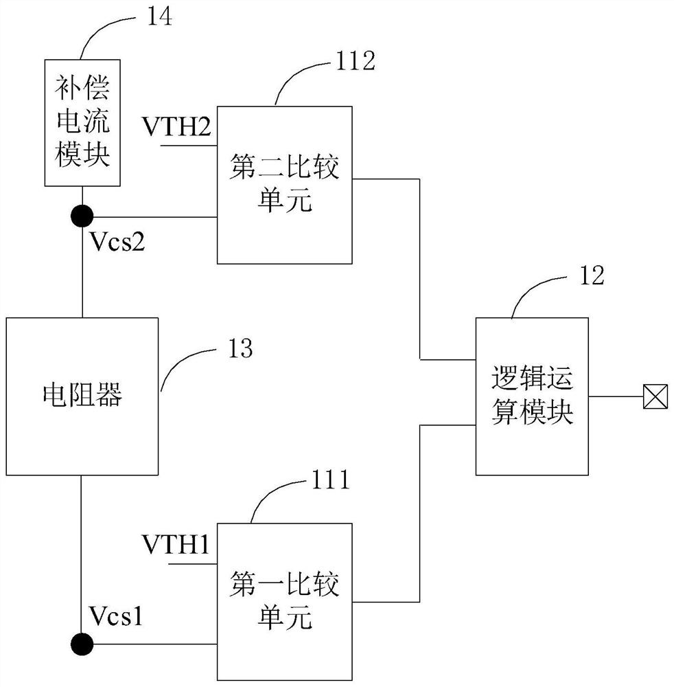
[0060] see Figure 9, the first comparison unit 111 may be the first comparator 1111, the second comparison unit 112 may be the second comparator 1121, the resistor may include the first resistor 131, the compensation current module 14 may include the compensation current unit 141, and the logic operation module 12 may include a first NAND gate 1231. The first resistor 131 is connected between the first input terminal of the first comparator 1111 and the first input terminal of the second comparator 1121, the second input terminal of the first comparator 1111 receives the first threshold voltage VTH1, the second The second input terminal of the comparator 1121 receives the second threshold voltage VTH2, the output terminal of the first comparator 1111 and the output terminal of the second comparator 1121 are respectively connected with the first input terminal and the second input terminal of the first NAND gate 1231 connect. The output end of the first NAND gate 1231 is con...
example 2
[0078] see Figure 11, compared with Example 1, the difference in this example is that the first comparison unit 111 includes a third comparator 1112, the second comparison unit 112 includes a fourth comparator 1122, the resistor 13 includes a second resistor 132, and the gate logic The unit includes a first NOT gate 1232 , a second NOT gate 1233 and a second NAND gate 1234 . The second resistor 132 is connected between the first input terminal of the third comparator 1112 and the first input terminal of the fourth comparator 1122. The second input terminal of the third comparator 1112 receives the first threshold voltage VTH1, and the fourth The second input terminal of the comparator 1122 receives the second threshold voltage VTH2, the output terminal of the third comparator 1112 and the output terminal of the fourth comparator 1122 are respectively connected with the input terminal of the first NOT gate 1232 and the input of the second NOT gate 1233 end connection. The ou...
Embodiment 2
[0082] A lighting control chip includes the lighting control circuit 100 of the first embodiment.
[0083] For the products provided by the embodiments of the present invention, for the purpose of brief description, for the parts not mentioned in the embodiments, reference may be made to the corresponding contents in the foregoing embodiments.
PUM
 Abstract
Description
Claims
Application Information
 - R&D
- Intellectual Property
- Life Sciences
- Materials
- Tech Scout
- Unparalleled Data Quality
- Higher Quality Content
- 60% Fewer Hallucinations
Browse by: Latest US Patents, China's latest patents, Technical Efficacy Thesaurus, Application Domain, Technology Topic, Popular Technical Reports.
© 2025 PatSnap. All rights reserved.Legal|Privacy policy|Modern Slavery Act Transparency Statement|Sitemap|About US| Contact US: help@patsnap.com