Cutter for cutting glass

A glass cutting and cutting tool technology, applied in glass cutting devices, glass manufacturing equipment, manufacturing tools, etc., can solve problems such as more wear and scratches at the cutting position, and achieve the effect of precise cutting and reducing wear and tear.

Active Publication Date: 2022-04-19
江门馗达特玻科技有限公司
View PDF5 Cites 0 Cited by
  • Summary
  • Abstract
  • Description
  • Claims
  • Application Information

AI Technical Summary

Problems solved by technology

[0002] In modern homes, people generally use glass as furniture, and then they need to cut the glass according to their needs. When people need to cut round glass, they need to place the glass on the workbench, and then use the cutting tool to automatically draw a circle, and the glass cutting process In the cut position, there are more scratches and wear

Method used


Image

  • Cutter for cutting glass
  • Cutter for cutting glass
  • Cutter for cutting glass

Examples


Embodiment 1

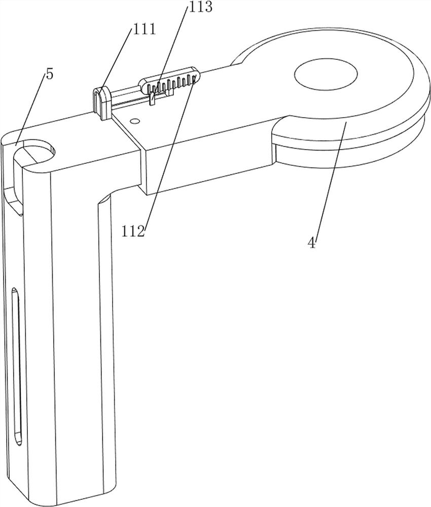
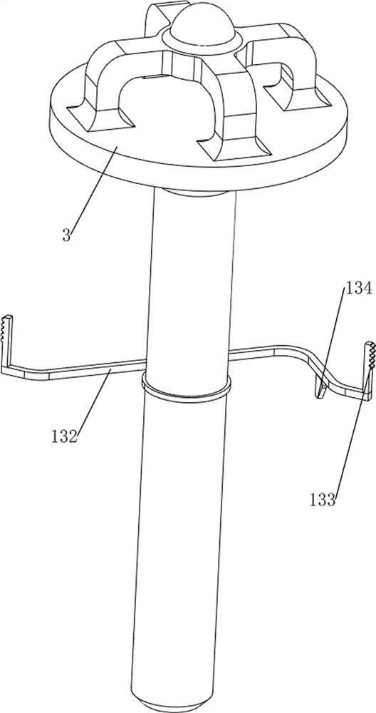
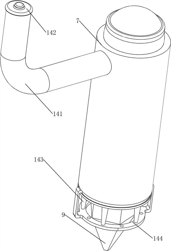
[0034] A glass cutting tool, such as Figure 1-6 As shown, it includes a first rubber 1, a support frame 2, a first fixed rod 3, a fixed frame 4, a movable frame 5, a first spring 51, a clamping rod 6, a shell 7, a sliding rod 8, a glass knife 9, a clamping Mechanism 10 and measuring mechanism 11, the lower side of the first fixed rod 3 is provided with a support frame 2, the bottom of the support frame 2 is provided with four first rubbers 1, the middle position of the first fixed rod 3 is rotatably provided with a fixed frame 4, and the fixed frame 4. The rear sliding type is provided with a movable frame 5, and the fixed frame 4 and the movable frame 5 are movablely provided with a clamping rod 6. The sliding type in the movable frame 5 is provided with a shell 7, and the shell 7 and the movable frame 5 are connected with a second A spring 51, the upper side of the casing 7 is symmetrically provided with a sliding rod 8, the sliding rods 8 are all slidably connected with th...

Embodiment 2

[0039]On the basis of Example 1, such as figure 1 , Figure 7 , Figure 8 , Figure 9 , Figure 10 , Figure 11 , Figure 12 , Figure 13 , Figure 14 with Figure 15 Shown, also comprise limit mechanism 12, limit mechanism 12 comprises the first fixed plate 121, rotating shaft 122, rotating frame 123, the 3rd spring 124, telescoping rod 125 and sponge 126, on the first fixed rod 3 rotary type There is a first fixed plate 121, the first fixed plate 121 is located on the upper side of the fixed frame 4, the first fixed plate 121 is provided with a rotating shaft 122 symmetrically rotated, and the rotating frame 122 is provided with a rotating frame 123, and the upper side of the rotating frame 123 slides The formula is provided with telescopic rod 125, and the ends of telescopic rod 125 are all provided with sponge 126, and the third spring 124 is all connected between telescopic rod 125 and rotating frame 123.

[0040] The user can rotate the rotating shaft 122 on bot...


PUM


Abstract

The invention relates to a cutter, in particular to a cutter for cutting glass. The invention aims to provide the cutter for cutting the glass, which can accurately cut the glass and cannot damage the glass during cutting. A cutter for glass cutting comprises first rubber, a supporting frame, a first fixing rod, a fixed frame, a movable frame, a clamping rod and a shell, the supporting frame is arranged on the lower side of the first fixing rod, the four pieces of first rubber are arranged at the bottom of the supporting frame, the fixed frame is rotatably arranged in the middle of the first fixing rod, and the movable frame is slidably arranged on the fixed frame; a clamping rod is movably arranged between the fixed frame and the movable frame, and a shell is arranged in the movable frame in a sliding mode. According to the glass cutting device, the effects that the glass can be accurately cut, and the glass cannot be damaged during cutting are achieved; according to the glass cutting device, the limiting mechanism is matched with the discharging mechanism, so that during cutting, the discharging mechanism drips glass cutting fluid on glass, and abrasion of the glass during cutting is reduced.

Description

technical field [0001] The invention relates to a cutter, in particular to a cutter for cutting glass. Background technique [0002] In modern homes, people generally use glass as furniture, and then they need to cut the glass according to their needs. When people need to cut round glass, they need to place the glass on the workbench, and then use the cutting tool to automatically draw a circle, and the glass cutting process In the cut position, there are more scratches and wear. [0003] Therefore, it is necessary to design a glass cutting tool that can accurately cut glass without damaging the glass. Contents of the invention [0004] In order to overcome the disadvantages that when people need to cut circular glass, the circle is automatically drawn by the cutting tool, and there are many scratches and wear at the cutting position during the glass cutting process, the technical problem of the present invention is: to provide a Glass cutting knives that cut without dam...

Claims


Application Information

Patent Timeline
Patent Type & Authority Applications(China)
IPC IPC(8): C03B33/00C03B33/12
CPCC03B33/00C03B33/12Y02P40/57
Inventor 张文锐
Owner 江门馗达特玻科技有限公司
Why Eureka
Try Eureka