Lamp module and substrate processing equipment

A technology for processing equipment and modules, applied in electrical components, semiconductor/solid-state device manufacturing, circuits, etc., can solve problems such as increased workload and economic costs, frequent cavity replacement of halogen lamps, large differences in service life, etc. The effect of workload and economic cost, saving control time, and easy control

Pending Publication Date: 2022-04-19
JIANGSU ALPHA-SEMICON EQUIP CO LTD
View PDF1 Cites 0 Cited by
  • Summary
  • Abstract
  • Description
  • Claims
  • Application Information

AI Technical Summary

Problems solved by technology

If the same power is applied to all the halogen lamps in the two lamp areas, in the actual process, the temperature of the outer ring of the substrate will be much higher than the temperature of the inner ring of the substrate; High uniformity, when it is necessary to apply different powers to the halogen lamps in the two lamp areas, it not only takes a lot of time to adjust the power distribution of the halogen lamps in the two lamp areas, but also due to the different power of the halogen lamps in the two lamp areas There is a large difference in power (the general power ratio is 1:2.5~1:3), which leads to a large difference in the service life of the halogen lamps in the two lamp areas, and then has to frequently open the cavity to replace the halogen lamp, which increases the workload and economic costs.
[0004] Moreover, in the existing substrate processing equipment, since the halogen lamp is placed horizontally, the filament of the halogen lamp will sag and tilt after a period of use. Since the deposition thickness of the film is very sensitive to the heating temperature, if some The filaments of halogen lamps are inclined, which will cause uneven temperature in the area heated by these several halogen lamps

Method used


Image

  • Lamp module and substrate processing equipment
  • Lamp module and substrate processing equipment
  • Lamp module and substrate processing equipment

Examples


Embodiment Construction

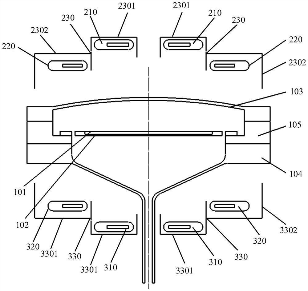
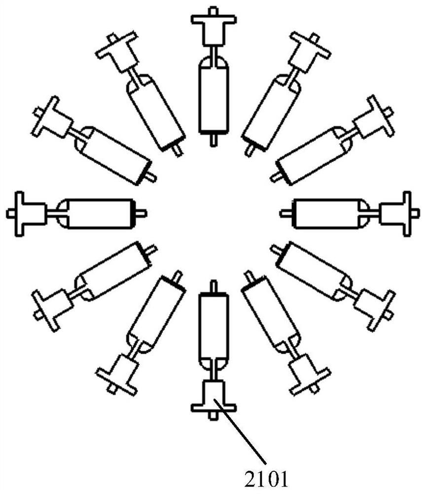
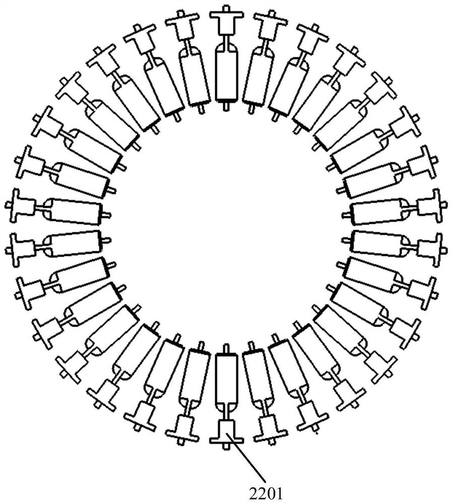
[0041] A lamp module and substrate processing equipment proposed by the present invention will be further described in detail below with reference to the drawings and specific embodiments. The advantages and features of the present invention will become clearer from the following description. It should be noted that the drawings are in a very simplified form and all use imprecise scales, which are only used to facilitate and clearly assist the purpose of illustrating the embodiments of the present invention. In order to make the objects, features and advantages of the present invention more comprehensible, please refer to the accompanying drawings. It should be noted that the structures, proportions, sizes, etc. shown in the drawings attached to this specification are only used to match the content disclosed in the specification, for those who are familiar with this technology to understand and read, and are not used to limit the implementation of the present invention. condi...


PUM

PropertyMeasurementUnit
diameteraaaaaaaaaa

Abstract

The invention discloses a lamp module and substrate processing equipment, an upper lamp module and/or a lower lamp module of the lamp module comprise/comprises an inner lamp group and an outer lamp group, the inner lamp group comprises a plurality of inner lamps, and all the inner lamps are circumferentially distributed; the outer lamp set comprises a plurality of outer lamps, and all the outer lamps are distributed in a circumferential mode. The number of inner lamps in the inner lamp set is 12, and the number of outer lamps in the outer lamp set is 30. The power ratio of one inner lamp to one outer lamp is (1: 1.1)-(1: 1.25); the upper lamp module and/or the lower lamp module further comprises an up-down adjusting device and a mounting device. Partition control can be performed on the surface temperature of the substrate, so that the uniformity of the surface temperature of the substrate is ensured, the cavity opening frequency is reduced, the inclination of the lamp filament can be effectively adjusted by the up-down adjusting device, the levelness of the lamp can be adjusted during installation, and the uniformity of the temperature is further ensured.

Description

technical field [0001] The invention relates to the technical field of semiconductor manufacturing, in particular to a lamp module and substrate processing equipment including the lamp module. Background technique [0002] Substrate processing equipment, such as epitaxial deposition equipment, is an important equipment in the semiconductor production process. Its function is mainly to deposit high-purity and high-performance films on the surface of the substrate (or wafer). For a thin film with uniform thickness, the substrate processing equipment must ensure the uniformity of the temperature distribution on the substrate surface during the heating process. [0003] Most of the existing substrate processing equipment uses a lamp module to heat the substrate. The lamp module usually includes an upper lamp module and a lower lamp module, wherein the upper lamp module usually includes 32 halogen lamps, and The 32 halogen lamps are evenly distributed on a circle with the same d...

Claims


Application Information

Patent Timeline
Patent Type & Authority Applications(China)
IPC IPC(8): H01L21/67
CPCH01L21/67115
Inventor 秦志坚燕春杨进
Owner JIANGSU ALPHA-SEMICON EQUIP CO LTD
Why Eureka
Try Eureka