Power distribution system of direct current charging equipment and direct current charging equipment

A DC charging and distribution system technology, applied in charging/discharging current/voltage regulation, charging stations, battery circuit devices, etc., can solve the problem of a single power distribution mode, and achieve multiple power distribution modes, convenient control, and overall balance. Good results

Pending Publication Date: 2022-04-19
ZHENGZHOU SENYUAN NEW ENERGY TECH +1
View PDF0 Cites 1 Cited by
  • Summary
  • Abstract
  • Description
  • Claims
  • Application Information

AI Technical Summary

Problems solved by technology

[0004] The purpose of the present invention is to provide a power distribution system of DC charging equipment and DC charging equipment, to solve the problem of single power distribution mode of existing DC charging equipment

Method used


Image

  • Power distribution system of direct current charging equipment and direct current charging equipment
  • Power distribution system of direct current charging equipment and direct current charging equipment
  • Power distribution system of direct current charging equipment and direct current charging equipment

Examples


Embodiment 1

[0050] The DC charging equipment is used in a split DC charging station in the form of a whole station, including a host and a charging pile, and a charging gun is provided on the charging pile. Among them, the host is used to realize AC-DC conversion and power distribution to form a power distribution system; the charging pile adopts a distributed layout to form a charging terminal (such as Figure 7 No. 1 sub-pile, No. 2 sub-pile ... No. 15 sub-pile); each charging post includes two charging guns, and each charging gun is connected to the DC charging device through the corresponding power supply circuit 12, located at Figure 7 The top is the first power supply circuit 12, which is located at Figure 7 The top one is the power supply circuit 12 at the end.

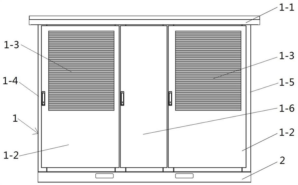
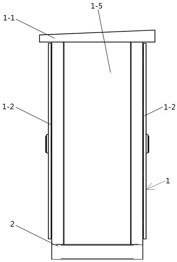
[0051] like figure 1 and figure 2 As shown, the host of the DC charging equipment adopts the form of a charging cabinet, including a base 2 and a cabinet 1, wherein the cabinet 1 is installed on the base 2, and the c...

Embodiment 2

[0079] The difference between this embodiment and Embodiment 1 is that in Embodiment 1, all the power modules in any group of homologous power supply groups are controlled as a whole through the module input contactors corresponding to the group of power modules, while this In the embodiment, each power module is individually controlled through a single-module contactor corresponding to each power module.

Embodiment 3

[0081] The difference between this embodiment and Embodiment 1 is that in Embodiment 1, the homologous power supply group is divided into two groups, while in this embodiment, each module group includes two power modules, and the homologous power supply group is divided into three groups. . Of course, in other embodiments, the same-source power supply group can also be divided into more than four groups.


PUM


Abstract

The invention relates to a power distribution system of direct current charging equipment and the direct current charging equipment. The direct current charging equipment comprises a charging pile and a power distribution system used for providing direct current for the charging pile, and the charging pile is provided with a charging gun; the power distribution system comprises power modules used for converting alternating current into direct current, each power module is connected with a power supply circuit used for supplying power to one corresponding charging gun, and/or at least two power modules form a module group, and the module group is connected with the power supply circuit. Each module group is connected with a power supply circuit for supplying power to one corresponding charging gun; and a power allocation switch is arranged between the at least two power supply circuits and is used for enabling the corresponding power supply circuits to form parallel connection so as to allocate the input power of the corresponding charging guns. The problem of single power distribution mode of the direct current charging equipment in the prior art can be solved.

Description

technical field [0001] The invention relates to the field of DC charging equipment, in particular to a power distribution system of the DC charging equipment. Background technique [0002] At present, the development of charging pile technology at home and abroad is uneven, and the main problems are as follows: [0003] For most of the charging equipment on the market, the power distribution mode is single, and the charging process is relatively simple. Effective and reasonable charging control strategies cannot be adopted according to the actual situation of the battery, which will easily cause waste of electric energy and affect the service life of the battery. In addition, in the operation process of high-power charging stations, due to the single power distribution mode, there are also problems such as single operation mode, unbalanced power distribution, large operation loss of the whole station, and even reactive power reversed to the grid under low load. Contents of...

Claims


Application Information

Patent Timeline
Patent Type & Authority Applications(China)
IPC IPC(8): H02J7/00B60L53/31B60L53/16
CPCH02J7/0013H02J7/007B60L53/31B60L53/16B60L2210/30Y02T10/70Y02T10/7072Y02T90/12Y02T90/14
Inventor 王伟名赵俊杰杨梦浩马丽娜王胜利卢峰波杨相玉押思梦
Owner ZHENGZHOU SENYUAN NEW ENERGY TECH
Why Eureka
Try Eureka