Moving coil loudspeaker

A horn and moving coil technology, which is applied to sensors, electrical components, and the fixing/tightening of the diaphragm, can solve the problems that the sound quality of the horn cannot be further improved, the air flow is uneven, etc., to achieve uniform flow, smooth vibration of the sound diaphragm, boost low frequency

Pending Publication Date: 2022-04-19
SHENZHEN YUANZE ELECTRONICS CO LTD
View PDF1 Cites 0 Cited by
  • Summary
  • Abstract
  • Description
  • Claims
  • Application Information

AI Technical Summary

Problems solved by technology

[0005] The purpose of the present invention is to provide a moving coil horn, which aims to solve the problem that when the vibrating membrane of the horn reciprocates in the prior art, it will push the air in the cavity between the vibrating membrane and the T iron to vibrate to generate airflow, and the airflow can only Entering and exiting the cavity from a position in the air hole in the center of the T-iron, resulting in uneven air flow in the cavity, resulting in a technical problem that the sound quality of the speaker cannot be further improved

Method used


Image

  • Moving coil loudspeaker
  • Moving coil loudspeaker
  • Moving coil loudspeaker

Examples


Embodiment Construction

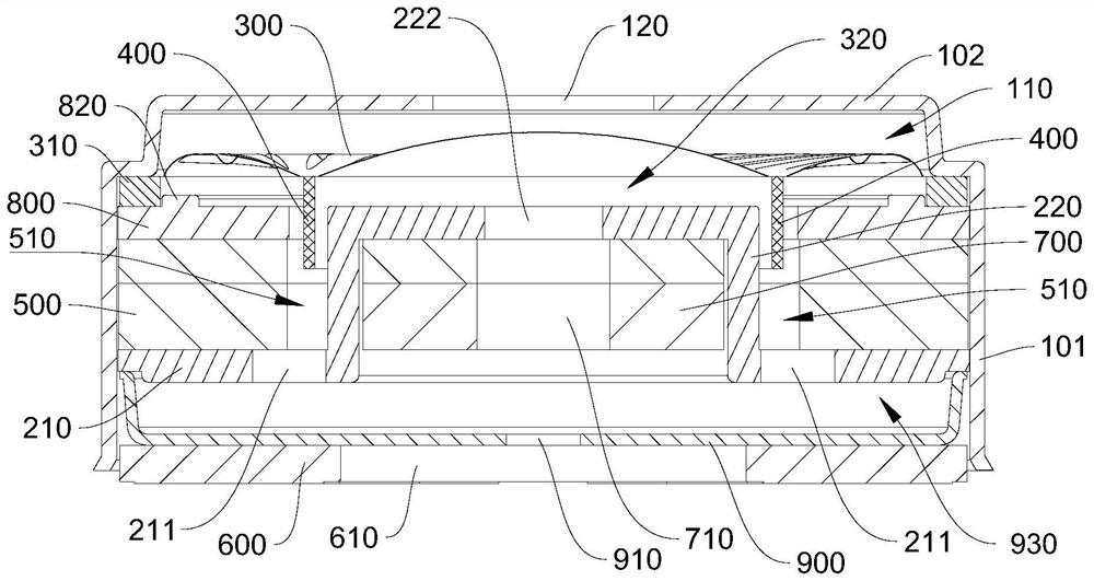
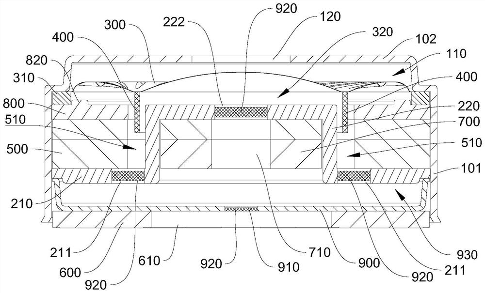
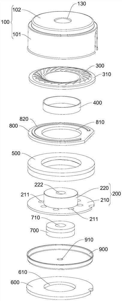
[0035] Embodiments of the present invention are described in detail below, examples of which are shown in the drawings, wherein the same or similar reference numerals designate the same or similar elements or elements having the same or similar functions throughout. The embodiments described below by referring to the figures are exemplary and are intended to explain the embodiments of the present invention and should not be construed as limitations of the present invention.

[0036] In the description of the embodiments of the present invention, it should be understood that the terms "length", "width", "upper", "lower", "front", "rear", "left", "right", "vertical ", "horizontal", "top", "bottom", "inner", "outer" and other indicated orientations or positional relationships are based on the orientations or positional relationships shown in the drawings, and are only for the convenience of describing the embodiments of the present invention and simplifying Describes, but does no...


PUM


Abstract

The invention belongs to the technical field of moving-coil loudspeakers, and particularly relates to a moving-coil loudspeaker which comprises a shell, T iron, a voice diaphragm, a voice coil, an outer magnet and a circuit board. A mounting cavity is formed in the shell, and a sound outlet and a mounting opening are formed in the two opposite ends of the shell respectively; a voice diaphragm, an outer magnet, T iron and a circuit board are sequentially mounted in the mounting cavity; the T iron comprises a bottom plate and a protrusion arranged in the middle of the bottom plate. An accommodating groove is formed between the outer magnet and the bulge; one end of the voice coil is connected with the voice diaphragm, and the other end of the voice coil is movably accommodated in the accommodating groove; a first through hole is formed in the middle of the protrusion in a penetrating mode, at least one second through hole is formed in the bottom plate in a penetrating mode, and the second through holes are communicated with the containing groove. When the voice diaphragm vibrates, air in the cavity between the voice diaphragm and the T iron is pushed to vibrate to generate airflow, and the airflow flows into or out of the cavity through the first through hole and the second through hole, so that the airflow in the cavity flows uniformly, the airflow generated by the vibration of the voice diaphragm in the cavity is balanced, the vibration of the voice diaphragm is smoother, and the tone quality of the loudspeaker is improved.

Description

technical field [0001] The invention belongs to the technical field of moving coil speakers, and in particular relates to a moving coil speaker. Background technique [0002] At present, dynamic speakers are widely used in products such as TVs, computers, audio, headphones, etc. The dynamic speakers convert the current frequency into sound. When the changing current passes through the coil, a changing magnetic field is generated, and the coil drives the sound film of the moving coil to vibrate. , the sound membrane pushes the air in the cavity to vibrate, thus producing sound. [0003] There are many kinds of dynamic speakers on the market. For example, the Chinese invention patent application number is CN201520280941.5, which discloses a high-quality dynamic speaker structure, including a shell, a diaphragm, a voice coil, a washer, a magnet, and a T iron. and a circuit board; wherein, the housing has a cylinder side wall and a bottom wall, the cylinder side wall and the bo...

Claims


Application Information

Patent Timeline
Patent Type & Authority Applications(China)
IPC IPC(8): H04R9/02H04R9/04H04R9/06H04R7/18
CPCH04R9/025H04R9/045H04R9/06H04R7/18
Inventor 何越
Owner SHENZHEN YUANZE ELECTRONICS CO LTD
Why Eureka
Try Eureka