
Active pipeline shunting device

A diverting device and active technology, applied in pipeline systems, gas/liquid distribution and storage, mechanical equipment, etc., can solve the problem that pipeline diversion cannot meet the variable flow distribution ratio, etc., and achieve convenient and accurate adjustment of diversion ratio. Improve anti-vibration High performance and wide adaptability

Pending Publication Date: 2022-04-22
NO 719 RES INST CHINA SHIPBUILDING IND
View PDF0 Cites 0 Cited by
  • Summary
  • Abstract
  • Description
  • Claims
  • Application Information

AI Technical Summary

Problems solved by technology

[0004] The invention provides an active pipeline diversion device, which is used to solve the defect that pipeline diversion in the prior art cannot meet the requirements of variable flow distribution ratios under different working conditions

Method used


Image

  • Active pipeline shunting device
  • Active pipeline shunting device
  • Active pipeline shunting device

Examples


Embodiment Construction

[0035] In order to make the purpose, technical solutions and advantages of the present invention clearer, the technical solutions in the present invention will be clearly and completely described below in conjunction with the accompanying drawings in the present invention. Obviously, the described embodiments are part of the embodiments of the present invention , but not all examples. Based on the embodiments of the present invention, all other embodiments obtained by persons of ordinary skill in the art without creative efforts fall within the protection scope of the present invention.

[0036] In the description of the embodiments of the present invention, it should be noted that, unless otherwise specified and limited, the terms "first", "second", "third" and "fourth" are used to clearly illustrate the numbering of product components. Does not represent any substantive difference. "Up", "Down", "Left" and "Right" are only used to indicate relative positional relationship. ...


PUM


Abstract

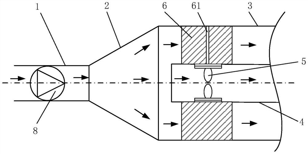
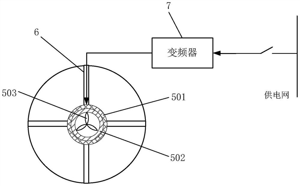
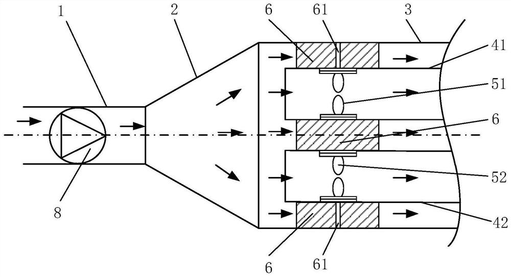
The invention provides an active pipeline flow dividing device which comprises a header pipe, a transition connecting pipe and a multi-flow-path pipe, the multi-flow-path pipe comprises an outer pipe and at least one inner pipe, the outer pipe is connected with the transition connecting pipe, and the inner pipe is arranged in the outer pipe in a penetrating mode and fixedly connected to the outer pipe; and a rim pump is mounted in each inner pipe. According to the active pipeline flow dividing device, under the condition that the flow of the main pipe is certain, the flow of the inner pipe can be independently controlled according to requirements through an additional pressure head provided by the rim pump located in the inner pipe, so that the flow proportion of the inner pipe and the outer pipe is adjusted, and the device is compact in structure, wide in adaptability and convenient and accurate in flow dividing proportion adjustment; operation control is simple and reliable.

Description

technical field [0001] The invention relates to the technical field of fluid pipeline transportation, in particular to an active pipeline diversion device. Background technique [0002] In the industrial field, it is often necessary to use pipelines for fluid transportation. In some cases, it is necessary to divide the pipelines to make them change from a single-flow flow to a multi-flow flow. The general flow structure mostly adopts passive flow, that is, branch pipelines The proportion of fluid flow distribution is constant, which can be uniform distribution or non-uniform distribution. [0003] However, for some conveying pipelines with different operating conditions, it is usually required that the fluid flow distribution ratios between the branch pipelines are different under different operating conditions. For example, for a shell-and-tube centralized heat exchanger, it mainly includes two cooling systems for heat exchange. The heat exchange between the inner pipe an...

Claims


Application Information

Patent Timeline
Patent Type & Authority Applications(China)
IPC IPC(8): F17D1/14F17D3/01
CPCF17D1/14F17D3/01
Inventor 庞杰王苇柯汉兵王瑞奇陈凯刘春林李邦明魏志国陈列
Owner NO 719 RES INST CHINA SHIPBUILDING IND
Learn More