Detection device and method for rigid contact network

A detection device and rigid contact technology, applied in the field of rail transit, can solve problems such as difficult access to auxiliary information, and achieve accurate detection results

Pending Publication Date: 2022-04-22
HANGZHOU SHENHAO TECH
View PDF1 Cites 0 Cited by
  • Summary
  • Abstract
  • Description
  • Claims
  • Application Information

AI Technical Summary

Problems solved by technology

[0004] In order to solve the above-mentioned problems in the prior art, the present invention provides a detection device and method for rigid catenary, which solves the problem that the existing detection method for rigid catenary cannot effectively judge whether it is the displacement of the loose connection of the channel steel position or the overall displacement, making it difficult to effectively monitor and acquire accurate auxiliary information

Method used


Image

  • Detection device and method for rigid contact network
  • Detection device and method for rigid contact network
  • Detection device and method for rigid contact network

Examples


Embodiment 1

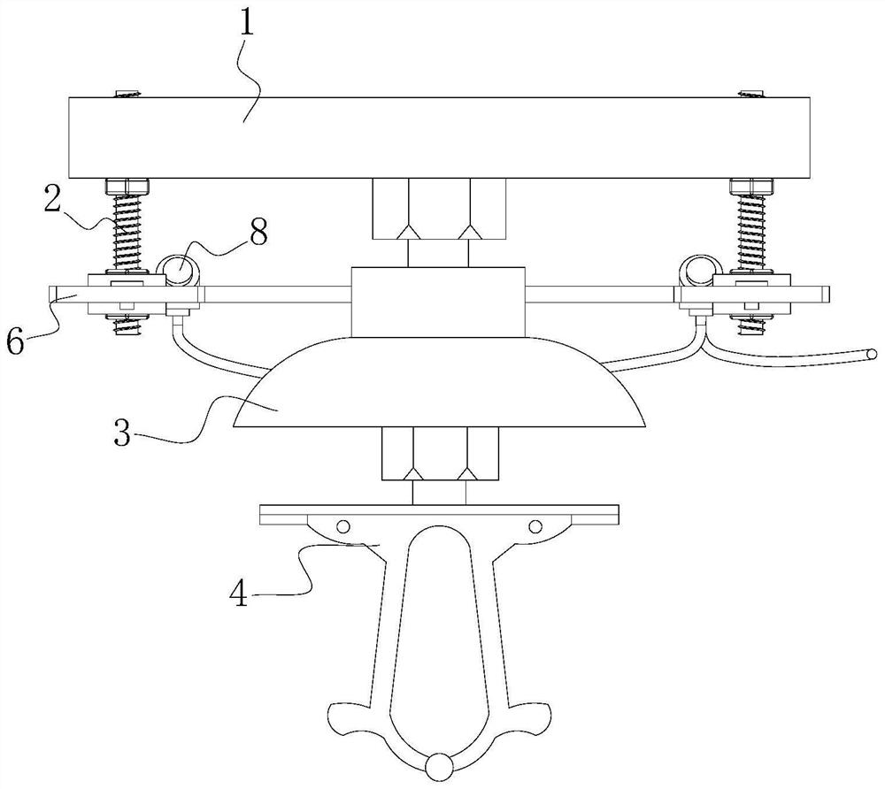
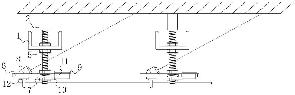
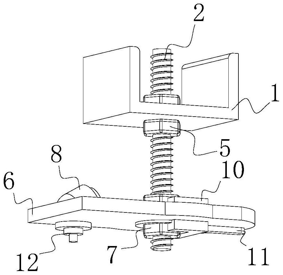
[0048] S1. Install the table plate 6 by adjusting the screw 7 according to the position of the bottom end of the anchor bolt 2 .

[0049] S2. Measure the distance between the platen 6 and the channel steel 1, and adjust the height of the platen 6 through the adjusting screw 7, and keep the platen 6 and the channel steel 1 at a constant distance to limit the adjustment bolt through the clip 10.

[0050] S3. After the installation is completed, the distance sensor 8 is sequentially connected to the track dispatching center through the terminal 12, and the distance sensor 8 is started to obtain initial measurement distance data.

[0051] S4. During the long-term operation, if the overall height of the anchor bolt 2 changes, the position of the distance sensor 8 is shifted from L1 to L2.

[0052] S5. It can be seen that the fixed elevation angle θ of the distance sensor 8 is 45°, and the difference between the measurement distance of the L2 position and the measurement distance of t...

Embodiment 2

[0056] S1. Install the table plate 6 by adjusting the screw 7 according to the position of the bottom end of the anchor bolt 2 .

[0057] S2. Measure the distance between the platen 6 and the channel steel 1, and adjust the height of the platen 6 through the adjusting screw 7, and keep the platen 6 and the channel steel 1 at a constant distance to limit the adjustment bolt through the clip 10.

[0058] S3. After the installation is completed, the distance sensor 8 is sequentially connected to the track dispatching center through the terminal 12, and the distance sensor 8 is started to obtain initial measurement distance data.

[0059] S4. During the long-term operation, if the overall height of the anchor bolt 2 changes, the position of the distance sensor 8 is shifted from L1 to L2.

[0060] S5. It can be seen that the fixed elevation angle θ of the distance sensor 8 is 90°, and the distance sensor 8 is kept below the channel steel 1 .

[0061] S6. While monitoring the overa...

Embodiment 3

[0064] S1. Install the table plate 6 by adjusting the screw 7 according to the position of the bottom end of the anchor bolt 2 .

[0065] S2. Measure the distance between the platen 6 and the channel steel 1, and adjust the height of the platen 6 through the adjusting screw 7, and keep the platen 6 and the channel steel 1 at a constant distance to limit the adjustment bolt through the clip 10.

[0066] S3. After the installation is completed, the distance sensor 8 is sequentially connected to the track dispatching center through the terminal 12, and the distance sensor 8 is started to obtain initial measurement distance data.

[0067] S4. During the long-term operation, if the overall height of the anchor bolt 2 changes, the position of the distance sensor 8 is shifted from L1 to L2.

[0068] S5. It can be seen that the fixed elevation angle θ of the distance sensor 8 is 90°, and the distance sensor 8 is kept staggered below the channel steel 1, so that the initial measurement...


PUM


Abstract

The invention relates to a detection device and method for a rigid contact network, and belongs to the technical field of rail transit, the detection device comprises channel steel, the lower surface of the channel steel is in threaded connection with two anchor bolts through two mounting screws, and by arranging a distance sensor, a bedplate, the channel steel and the anchor bolts, when the detection device is used, the bedplate and the channel steel are located at the constant distance position; when the channel steel is vibrated by the busbar conductive assembly, the bolt mounting position of the channel steel is loosened, and the distance sensor is shielded when the height of the channel steel is changed, so that the overall connection state can be detected, and meanwhile, the bolt connection looseness of the channel steel position and the connection looseness of the anchor bolt and the interior of the tunnel can be judged to realize accurate distinguishing; according to data measurement of different nodes, when out-of-range distance data appears, the track dispatching center gives an alarm, maintenance is carried out at the first time, and in this way, accurate fault information can be effectively obtained while accurate detection is achieved.

Description

technical field [0001] The invention relates to the technical field of rail transit, in particular to a detection device and method for a rigid catenary. Background technique [0002] The overhaul of the catenary found that because the rigid catenary has many connection points in contact with the suspension parts, the impact force of the pantograph caused the overall vibration of the Huliu school conductive components and the channel steel, and it was basically connected by bolts. The phenomenon of loosening occurs continuously under the impact and vibration, which makes the contact part heat up and accelerates the oxidation process of the metal conductor, thereby greatly increasing the contact resistance and making the heating more serious. If things go on like this, the temperature will increase sharply, eventually burning red and melting, thereby damaging the equipment and causing accidents. For this purpose, the publication number of a detection device for the connection...

Claims


Application Information

Patent Timeline
IPC IPC(8): G01B21/02
CPCG01B21/02
Inventor 王磊邓成呈陈如申黎勇跃
Owner HANGZHOU SHENHAO TECH
Why Eureka
Try Eureka