
Beam body pre-camber measuring device

A measuring device and pre-camber technology, applied in the direction of measuring device, elasticity test, machine/structural component test, etc., can solve the problems of low accuracy, low practicability, low efficiency, etc. The effect of improving measurement accuracy and high practicability

Pending Publication Date: 2022-04-22
中铁九局集团第五工程有限公司
View PDF0 Cites 0 Cited by
  • Summary
  • Abstract
  • Description
  • Claims
  • Application Information

AI Technical Summary

Problems solved by technology

[0004] However, the existing beam body pre-camber measurement device mainly lays the same horizontal datum plane on the bottom of the beam body and measures the height of each point between the bottom surface of the beam body and the horizontal datum plane through laser measurement or other measuring tools, so as to pass multi-point Measure and construct a complete beam bottom surface model. This measurement method is cumbersome to operate, and the accuracy of the measurement results varies with the frequency of operations. The fewer points to measure, the higher the chance of the results, resulting in cumbersome and inaccurate measurement steps. The camber of the bottom surface of the beam body is complete, and the practicability is low
In view of this, the existing problems are studied and improved, and a beam body pre-camber measurement device is provided to solve the existing problems of cumbersome measurement operations, low efficiency and low accuracy, aiming to solve the problem through this technology and the purpose of improving practical value

Method used


Image

  • Beam body pre-camber measuring device
  • Beam body pre-camber measuring device
  • Beam body pre-camber measuring device

Examples


Embodiment Construction

[0036] In order to make the object, technical solution and advantages of the present invention clearer, the present invention will be further described in detail below in combination with specific embodiments and with reference to the accompanying drawings. It should be noted that, in the case of no conflict, the embodiments of the present invention and the features in the embodiments can be combined with each other.

[0037] It is understood that these descriptions are exemplary only, and are not intended to limit the scope of the invention.

[0038] A beam body pre-camber measurement device provided by some embodiments of the present invention is described below with reference to the accompanying drawings.

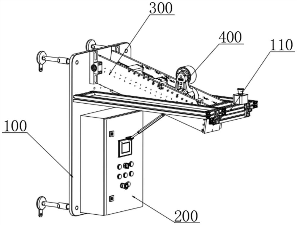
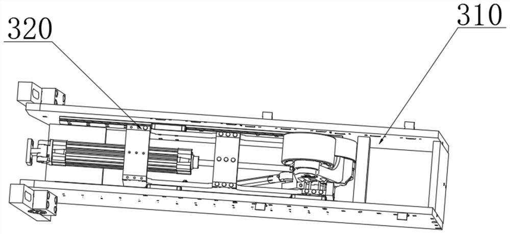
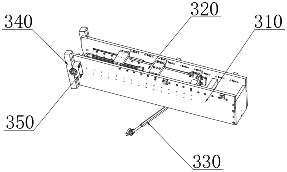
[0039] combine Figure 1-6 As shown, a beam body pre-camber measurement device provided by the present invention includes: a fixed base plate 100, a control terminal 200, a measurement drive assembly 300 and a deflection angle measurement assembly 400, and the control ter...


PUM

PropertyMeasurementUnit
Thicknessaaaaaaaaaa

Abstract

A beam body pre-camber measuring device disclosed by the present invention comprises a fixed substrate, a control terminal, a measurement driving assembly and a deflection angle measuring assembly, the control terminal and the measurement driving assembly are fixedly installed on one side of the fixed substrate, and a horizontal calibration frame is fixedly installed on the side surface of the fixed substrate. The deflection angle measurement assembly is fixedly installed at the output end of the measurement driving assembly, and the output end of the deflection angle measurement assembly is electrically connected with the input end of the control terminal. According to the invention, the motion type monitoring structure is arranged, the translational motion of the deflection angle measuring assembly is utilized to be attached to the bottom surface of the beam body, the inclination amount of the deflection rocker arm is converted into the deformation amount of the camber of the bottom surface of the beam body through the inclination angle sensor, and the comprehensive camber curve of the bottom surface of the beam body is completely reflected in the translational motion; the camber value of each point is accurately reflected, and the practicability of the measuring device is improved.

Description

technical field [0001] The invention relates to the technical field of highway and bridge engineering, in particular to a beam body pre-camber measurement device. Background technique [0002] The causes of bridge deflection include permanent action deflection and variable load deflection. The permanent action includes the gravity of the structure, bridge deck pavement and ancillary equipment, prestress, concrete creep and shrinkage. Duration-related, it can be divided into short-term deflection and long-term deflection. The permanent deflection can be offset by the preset reverse deflection during construction, also known as pre-camber, so that the completed bridge can achieve ideal linearity. [0003] The pre-camber of prestressed concrete bridges is usually set according to the following regulations: when the long-term anti-camber value generated by pre-stress is greater than the long-term deflection calculated according to the combination of short-term load effects, no p...

Claims


Application Information

Patent Timeline
IPC IPC(8): G01M5/00G01B21/32
CPCG01M5/0008G01M5/005G01B21/32
Inventor 郭金龙梁彦峰王志远张旭华郭景生马云鹏杨柳沈云飞
Owner 中铁九局集团第五工程有限公司
Learn More