
Three-dimensional space vector magnetic measurement device and method

A three-dimensional space and magnetic device technology, applied in the direction of the size/direction of the magnetic field, can solve the problems of the sample magnetization environment with limited stability and excitation efficiency, the inability to simulate three-dimensional dynamic magnetic characteristics, and the difficulty in improving the sensitivity of H sensing. Achieve the effect of avoiding low material utilization rate, good application and promotion value, and improving design method

Active Publication Date: 2022-04-22
HEBEI UNIV OF TECH
View PDF9 Cites 0 Cited by
  • Summary
  • Abstract
  • Description
  • Claims
  • Application Information

AI Technical Summary

Problems solved by technology

However, the induction coil is susceptible to extrusion deformation and poor stability in high-frequency environments
In addition, the distance between the induction H coil and the surface of the sample is limited by the existing technology, which is difficult to close to 0 and the consistency of each coil is poor. Limited by the sample test space, it is difficult to improve the sensitivity of the H sensor. The three-dimensional magnetic characteristic test device is single-axis (X-axis or Y-axis or Z-axis) Pole head position regulation stability and excitation efficiency are limited Sample magnetization environment
In addition, for the magnetization environment of actual working conditions, the existing technology cannot simulate the three-dimensional dynamic magnetic properties of the sample under stress

Method used


Image

  • Three-dimensional space vector magnetic measurement device and method
  • Three-dimensional space vector magnetic measurement device and method
  • Three-dimensional space vector magnetic measurement device and method

Examples


Embodiment Construction

[0030] In order to enable those skilled in the art to better understand the technical solutions of the present invention, the present invention will be further described in detail below in conjunction with the accompanying drawings and preferred embodiments. Based on the embodiments of the invention, all other embodiments obtained by persons of ordinary skill in the art without making creative efforts belong to the protection scope of the invention.

[0031] In the description of the invention, it should be noted that the terms "centre", "upper", "lower", "left", "right", "vertical", "horizontal", "inner", "outer", etc. indicate The orientation or positional relationship is based on the orientation or positional relationship shown in the drawings, which are only for the convenience of describing the invention and simplifying the description, rather than indicating or implying that the referred device or element must have a specific orientation, be configured in a specific orien...


PUM


Abstract

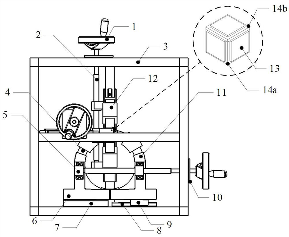
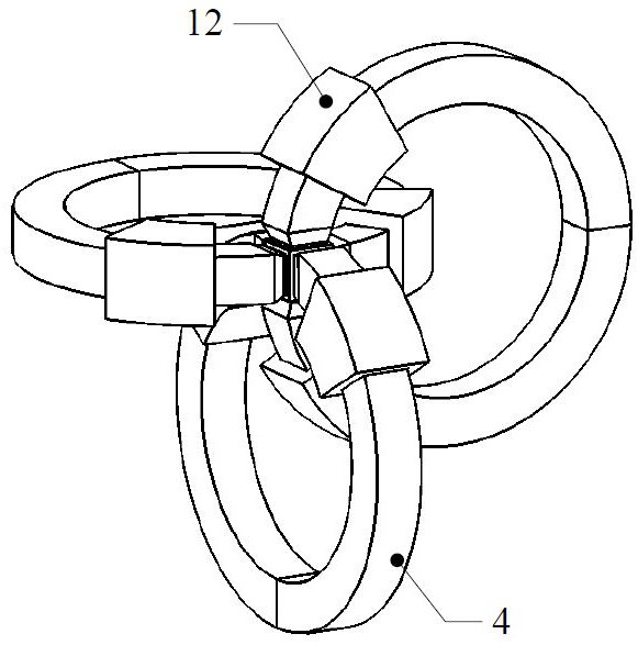
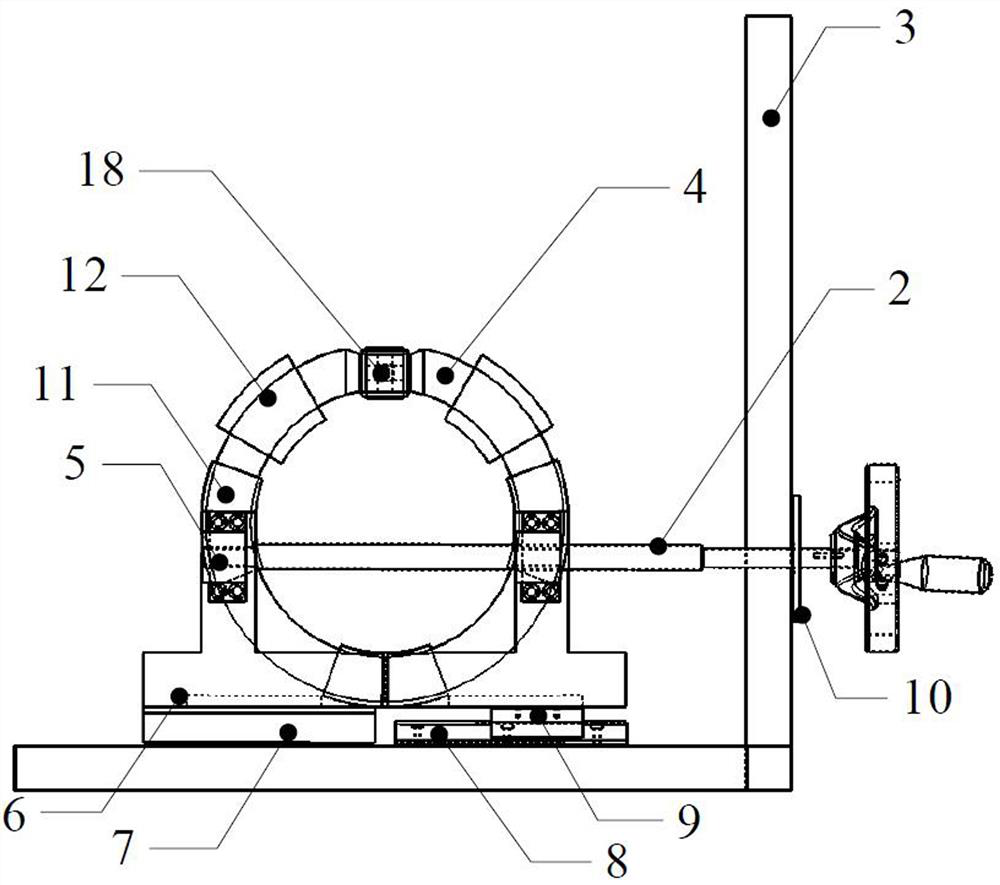
The invention relates to a three-dimensional space vector magnetic measurement device and method.The three-dimensional space vector magnetic measurement device comprises a main support, three iron core assemblies and a sample loading assembly, and each iron core assembly comprises two oppositely-arranged half iron cores, windings arranged on the half iron cores, iron core fixing pieces fixedly connected with the two half iron cores respectively and a driving part connected with the iron core fixing pieces; the driving part can adjust the distance between the two half iron cores, the sample loading assembly comprises a sample support, a sample body and a shielding block, the shielding block is arranged between the iron core pole heads of the half iron cores and the sample body, and a piezoelectric sensing piece or a piezoelectric stress ceramic piece is tightly connected between the shielding block and the sample body in an abutting mode. The problems that in an existing test method, the test reliability is poor, the sample magnetization efficiency is low and the actual working condition magnetization environment cannot be simulated due to the fact that the magnetization environment affects the magnetic-electricity relation are solved, and the problems that the material utilization rate is low and energy consumption is high due to the fact that a magnetic material model is inaccurate are solved.

Description

technical field [0001] The invention relates to the technical field of magnetic material testing, in particular to a three-dimensional space vector magnetic measuring device and method. Background technique [0002] The magnetic properties of magnetic materials are divided into static magnetic properties and dynamic magnetic properties. The static magnetic properties are related to the composition and structure of the material. Commonly used measurement methods include the impact method and the fluxmeter method. The dynamic magnetic properties are related to the magnetization environment of the material (such as excitation waveform, temperature, stress, frequency, etc.), the shape of the sample, and the processing technology. The commonly used measurement methods include the Epstein square method and the ring sample method. [0003] According to the boundary conditions of the magnetic field, when the distance between the sensing coil and the sample surface is infinitely clo...

Claims


Application Information

Patent Timeline
Patent Type & Authority Applications(China)
IPC IPC(8): G01R33/02
CPCG01R33/0206
Inventor 李永建郭鹏林志伟张长庚穆生辉
Owner HEBEI UNIV OF TECH
Learn More