Single-side floating eliminating structure of rotating shaft

A rotating shaft and unilateral technology, applied in the field of rotating shaft floating elimination structure, can solve the problems of radial and axial interference, affecting the effect of rotating shaft elimination, unstable use, etc., and achieve the effect of reducing friction

Pending Publication Date: 2022-04-22
浙江亚微精密机床有限公司
View PDF1 Cites 0 Cited by
  • Summary
  • Abstract
  • Description
  • Claims
  • Application Information

AI Technical Summary

Problems solved by technology

[0004] However, the axial floating of the rotating shaft is eliminated by paired angular contact ball bearings. Since the angular contact ball bearings are used to eliminate the radial and axial floating of the rotating shaft at the same time, during use, the radial and axial movement of the angular contact ball bearings There will be interference in the direction, which will affect the effect of eliminating the axial and radial floating of the shaft. It is unstable during use, and the shaft will generate a lot of heat due to friction during the rotation process, which will cause the device to overheat and affect the use of the device.

Method used


Image

  • Single-side floating eliminating structure of rotating shaft
  • Single-side floating eliminating structure of rotating shaft
  • Single-side floating eliminating structure of rotating shaft

Examples


Embodiment 1

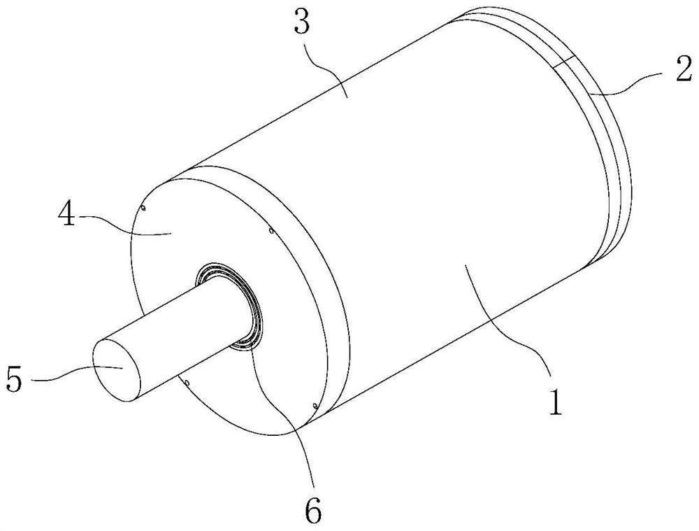
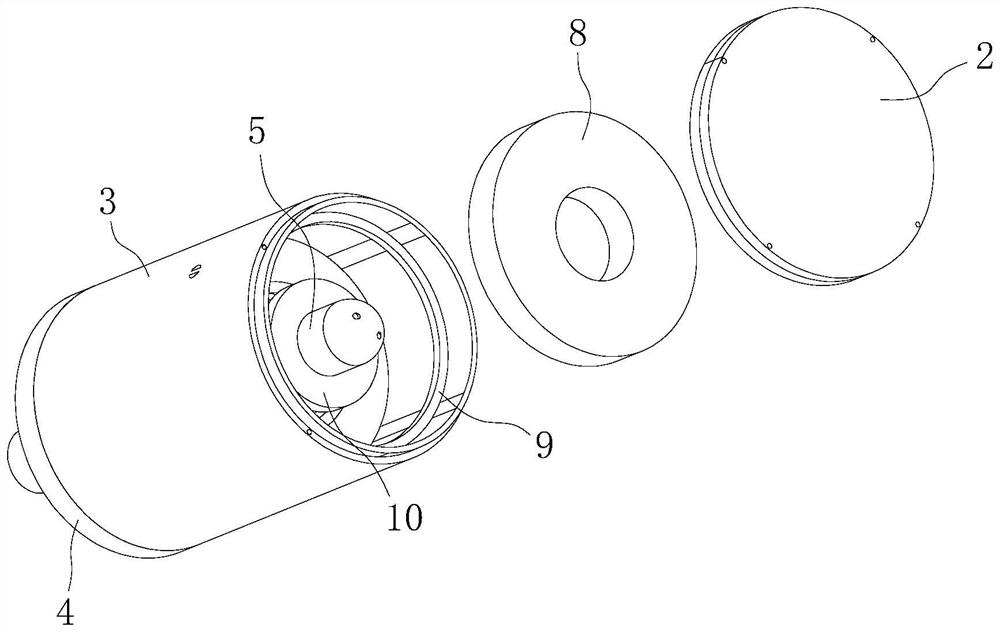
[0041] Figure 1-Figure 9 As shown, the floating elimination structure on one side of the rotating shaft includes a rotating shaft 5 , a magnetic attraction device 8 , an axial supporting member 20 and at least two sets of bearings 6 .

[0042] The rotating shaft 5 is rotatably arranged on the support 25. Preferably, the support 25 is the electric spindle casing 1, and the electric spindle casing 1 is a component on the existing electric spindle.

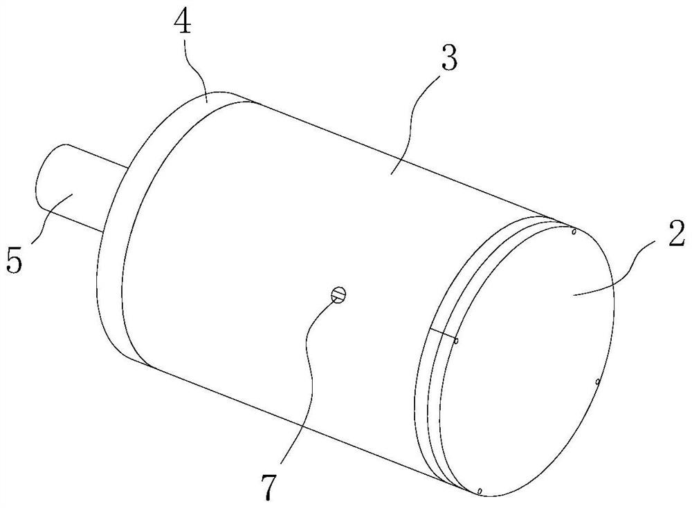
[0043] figure 1 , figure 2 , Figure 4 As shown, the above-mentioned rotating shaft 5 is arranged in the electric spindle casing 1, and the end of the front end of the rotating shaft 5 passes through the electric spindle casing 1. Specifically, the electric spindle casing 1 includes a main casing 3 and a main casing connected to the main casing. The front end cover 4 at the front end of the body 3, the front end cover 4 is fixedly connected to the front end of the main housing 3 by screws, the center of the front end cover 4 is ...

Embodiment 2

[0073] Figure 10-Figure 13 As shown, the floating elimination structure on one side of the rotating shaft includes a rotating shaft 5 , a magnetic attraction device 8 , an axial supporting member 20 and at least two sets of bearings 6 .

[0074] The rotating shaft 5 is rotatably arranged on the support 25. Preferably, the support 25 is the electric spindle casing 1, and the electric spindle casing 1 is a component on the existing electric spindle.

[0075] The above-mentioned rotating shaft 5 is arranged in the electric spindle casing 1, and the end of the front end of the rotating shaft 5 passes through the electric spindle casing 1. Specifically, the electric spindle casing 1 includes a main casing 3 and a front end connected to the main casing 3. The front end cover 4 is fixedly connected to the front end of the main housing 3 by screws, the center of the front end cover 4 is provided with a through hole 11, and the rotating shaft 5 in the electric spindle casing 1 is conn...

Embodiment 3

[0105] Figure 14 As shown, the rotating shaft 5 in the above embodiment can also be a screw rod, and the axial floating of the screw rod can be eliminated through the mutual cooperation of the above-mentioned blocking member 18 and the axial support member 20, and the friction suffered by the screw rod when rotating can be reduced. force, through at least two sets of bearings 6 set on the screw rod to eliminate the radial floating of the screw rod.


PUM


Abstract

The invention discloses a single-side floating eliminating structure of a rotating shaft, and belongs to the field of rotating shaft floating eliminating structures, the single-side floating eliminating structure of the rotating shaft comprises the rotating shaft, a magnetic attraction device, an axial jacking piece and at least two sets of bearings, the rotating shaft is arranged on a support, the at least two sets of bearings sleeve the rotating shaft to limit radial floating of the rotating shaft, and the magnetic attraction device has magnetic force and is arranged on the single side of the rotating shaft; the magnetic attraction device is fixed to the support and combined with the support to form a blocking component with magnetic force, the blocking component can apply magnetic attraction force to the rotating shaft to pull the rotating shaft towards one side in the axial direction, and therefore floating of the rotating shaft in the axial direction is limited, and the axial jacking piece is arranged between the end face of the rotating shaft and the blocking component. The axial jacking piece is used for making contact with the rotating shaft and the blocking component and reducing friction force borne by the rotating shaft during rotating of the rotating shaft.

Description

technical field [0001] The invention relates to the field of floating elimination structure of a rotating shaft, in particular to a floating eliminating structure on one side of a rotating shaft. Background technique [0002] The existing rotating shaft is installed on the bracket in rotation, such as the electric spindle, which is composed of a shellless motor, a rotating shaft, a bearing, a spindle unit shell, a drive module and a cooling device, etc. The rotor of the motor is integrated with the rotating shaft by a press-fitting method , the rotating shaft is supported by the front and rear bearings, and the stator of the motor is installed in the housing through the cooling jacket. The existing problem is that when the rotating shaft is in use, due to problems such as assembly or excessive clearance, it is easy to cause axial, radial and oblique floating of the rotating shaft, causing the center of the rotating shaft to shift, thereby affecting the use of the rotating sh...

Claims


Application Information

Patent Timeline
IPC IPC(8): H02K7/00H02K7/08
CPCH02K7/003H02K7/08
Inventor 潘旭华
Owner 浙江亚微精密机床有限公司
Why Eureka
Try Eureka