Lumbar vertebra rehabilitation relieving device for neurosurgery department
A technique of neurosurgery and lumbar spine, applied in massage auxiliary products, physical therapy, gymnastics equipment, etc., can solve problems that consume a lot of time and energy
- Summary
- Abstract
- Description
- Claims
- Application Information
AI Technical Summary
Problems solved by technology
Method used
Image
Examples
Embodiment 1
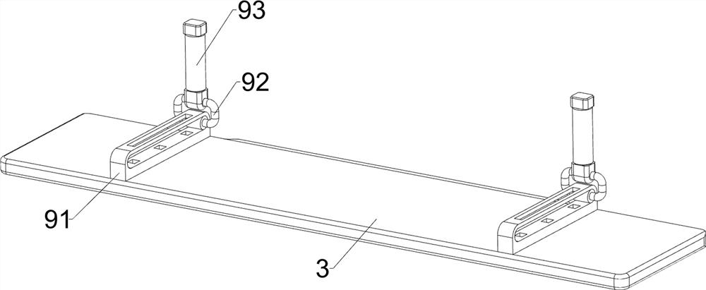
[0026] A neurosurgery lumbar spine rehabilitation relief device, such as Figure 1-8 As shown, it includes a frame 1, a support rod 2, a seat plate 3, a cover shell 4, a fixing assembly 5 and a backrest assembly 6, and two support rods 2 are arranged on the left and right sides of the frame 1, and between the upper parts of the support rods 2 A seat board 3 is provided, a cover shell 4 is connected between the frame 1 and the seat board 3 , a fixing assembly 5 is provided at the rear of the frame 1 , and a backrest assembly 6 is provided at the front of the frame 1 .
[0027] When using the device, the patient sits on the seat board 3, the feet are fixed by the fixing assembly 5, and the back rests on the backrest assembly 6, and the patient's lumbar spine is recovered and relieved by the backrest assembly 6.
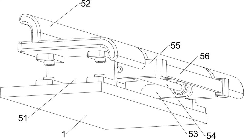
[0028] Such as figure 1 , figure 2 and Figure 5 As shown, the fixed assembly 5 includes a first fixed plate 51, a pedal 52, a support plate 53, a rotating shaft 54...
Embodiment 2
[0033] On the basis of Example 1, such as figure 1 , Figure 4 and Figure 7 As shown, push assembly 7 is also included, and push assembly 7 includes guide rail 71, sliding frame 72, first spring 73, cam 74, strip plate 75 and torsion spring 76, and frame 1 front left and right sides are all provided with Guide rail 71, sliding type is provided with slide frame 72 between two guide rails 71 of left and right sides, is all connected with first spring 73 between guide rail 71 and slide frame 72, and fixed frame 62 bottom, left and right sides are all provided with cam 74, and cam 74 all is equipped with. Cooperate with the sliding frame 72 , the rotating shaft 54 is provided with a strip plate 75 , the strip plate 75 cooperates with the sliding frame 72 , and a torsion spring 76 is wound between the support plate 53 and the rotating shaft 54 .
[0034] When using the device, the rotating plate 63 rotates downwards to drive the cam 74 to rotate. When the cam 74 rotates to c...
PUM
 Abstract
Description
Claims
Application Information
 - R&D
- Intellectual Property
- Life Sciences
- Materials
- Tech Scout
- Unparalleled Data Quality
- Higher Quality Content
- 60% Fewer Hallucinations
Browse by: Latest US Patents, China's latest patents, Technical Efficacy Thesaurus, Application Domain, Technology Topic, Popular Technical Reports.
© 2025 PatSnap. All rights reserved.Legal|Privacy policy|Modern Slavery Act Transparency Statement|Sitemap|About US| Contact US: help@patsnap.com


