
Mining machining extrusion device

A technology of mechanical processing and extrusion device, applied in the field of ore processing, can solve the problems of blockage of the discharge port, affecting the efficiency of processing and extrusion, and the inability of the ore to reach the crushing degree, so as to avoid damage and prolong the service life.

Active Publication Date: 2022-04-26
SHANDONG HUALIAN MINING
View PDF15 Cites 0 Cited by
  • Summary
  • Abstract
  • Description
  • Claims
  • Application Information

AI Technical Summary

Problems solved by technology

[0004] Aiming at the deficiencies of the prior art, the present invention provides a mining mechanical processing extrusion device, which has the advantages of automatic reset of falling buffer, three-axis meshing extrusion and gravity self-control discharge speed, and solves the problem of a large number of ore falling in the background technology. The resulting falling force will impact the extrusion roller inside the device. For a long time, it will cause cracks on the surface of the extrusion roller and speed up the damage of the extrusion roller. Maintenance will take a lot of time and affect the efficiency of processing and extrusion. Existing During the extrusion process of the processing extrusion device, when encountering an ore that looks like a sphere as a whole, it is very easy for the extrusion roller to fail to find the extrusion force point, so that the ore cannot reach the set degree of crushing, which affects the quality of extrusion and the existing After processing and extrusion of a large amount of ore, the crushed stone will be directly discharged from the discharge port. The instantaneous discharge of a large amount of crushed stone will cause the problem of blockage of the discharge port.

Method used


Image

  • Mining machining extrusion device
  • Mining machining extrusion device
  • Mining machining extrusion device

Examples


Embodiment Construction

[0024] The following will clearly and completely describe the technical solutions in the embodiments of the present invention with reference to the accompanying drawings in the embodiments of the present invention. Obviously, the described embodiments are only some, not all, embodiments of the present invention. Based on the embodiments of the present invention, all other embodiments obtained by persons of ordinary skill in the art without making creative efforts belong to the protection scope of the present invention.

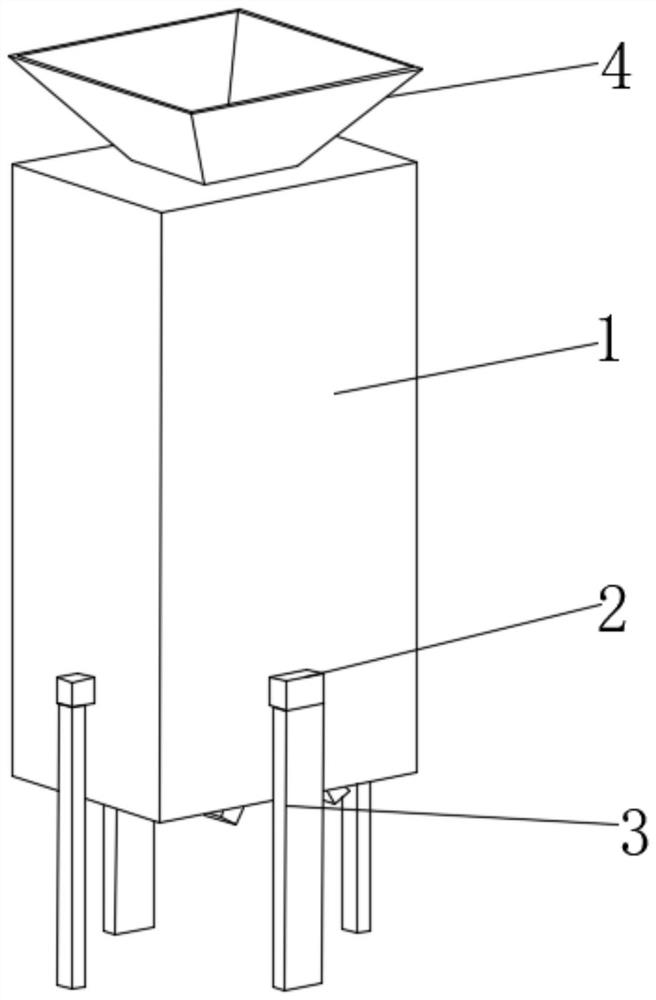
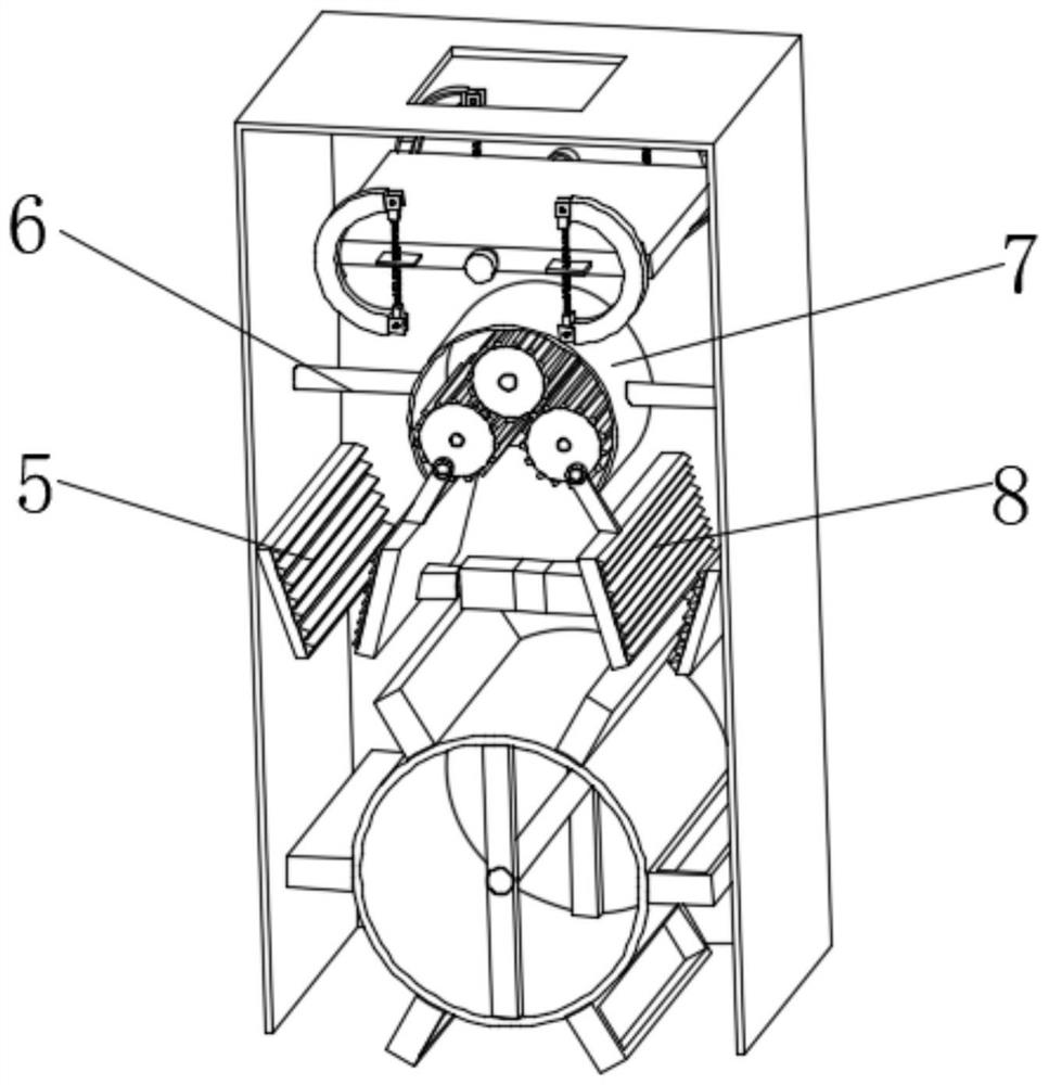
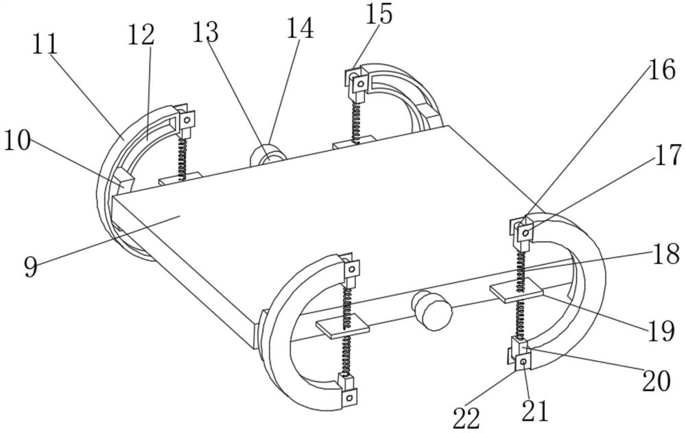
[0025] see Figure 1-6, a mining mechanical processing extrusion device, comprising an extrusion equipment shell 1, the two sides of the inner wall of the extrusion equipment shell 1 are fixedly installed with a second connection sleeve 14, and the inside of the second connection sleeve 14 is movable and connected with a connection Column 13, the side of the connecting column 13 is fixedly connected with a buffer plate 9, and the connecting column 13 on both s...


PUM


Abstract

The invention relates to the technical field of ore processing, and discloses a mining machining extrusion device which comprises an extrusion equipment shell, and second connecting sleeve shells are fixedly mounted on the two sides of the inner wall of the extrusion equipment shell. According to the mining machining extrusion device, fixing plates on the two sides of a buffer plate generate acting force on a reset spring to contract, and in the contraction process of the reset spring, a fixing sleeve shell fixedly installed on a first connecting block at the top rotates on the surface of a connecting shaft fixedly clamped in a connecting groove formed in a second connecting block; a reset spring can rotate and contract along with a sliding track in the sliding process of the arc-shaped sliding block, and when no ore falls down, under the action of the reset spring, a buffer plate drives the arc-shaped sliding block to reset to the original position in an arc-shaped ring groove of a semi-arc-shaped connecting sleeve shell, and the ore is prevented from falling off. And a buffer plate is arranged to bear falling of the ore and buffer falling acting force, damage to the interior of the device caused by direct falling of the ore is avoided to the maximum extent, and the overall service life is prolonged.

Description

technical field [0001] The invention relates to the technical field of ore processing, in particular to a mining mechanical processing extrusion device. Background technique [0002] Ore refers to mineral aggregates from which useful components can be extracted or have certain properties that can be used. It can be divided into metallic minerals and non-metallic minerals. The ores mined in mining areas are all raw stones, which require processing and extrusion equipment Carry out preliminary processing. As the main equipment for mining, it mainly crushes stones of different sizes. It can crush the raw ore mined in the process of processing metal ore and non-metallic ore by extrusion. The pulverized material into small particles can be divided into coarse crushing, medium crushing and fine crushing according to actual needs. The existing processing and extrusion equipment is small in size, easy to operate, easy to install and maintain, and the crushed ore can be used in It i...

Claims


Application Information

Patent Timeline
Patent Type & Authority Applications(China)
IPC IPC(8): B02C1/04B02C23/02B02C23/00B02C23/04
CPCB02C1/04B02C23/02B02C23/00B02C23/04Y02P70/10
Inventor 文增生张纪伟翟培用
Owner SHANDONG HUALIAN MINING
Learn More