Cable reel moving device for shipborne mobile emergency denial vehicle
A mobile device and cable reel technology, which is applied in the directions of transportation and packaging, thin material handling, and delivery of filamentous materials, etc., can solve the problems of manpower consumption and low efficiency, and achieve convenient movement, improved flexibility, and convenient adjustment Effect
- Summary
- Abstract
- Description
- Claims
- Application Information
AI Technical Summary
Problems solved by technology
Method used
Image
Examples
Embodiment 1
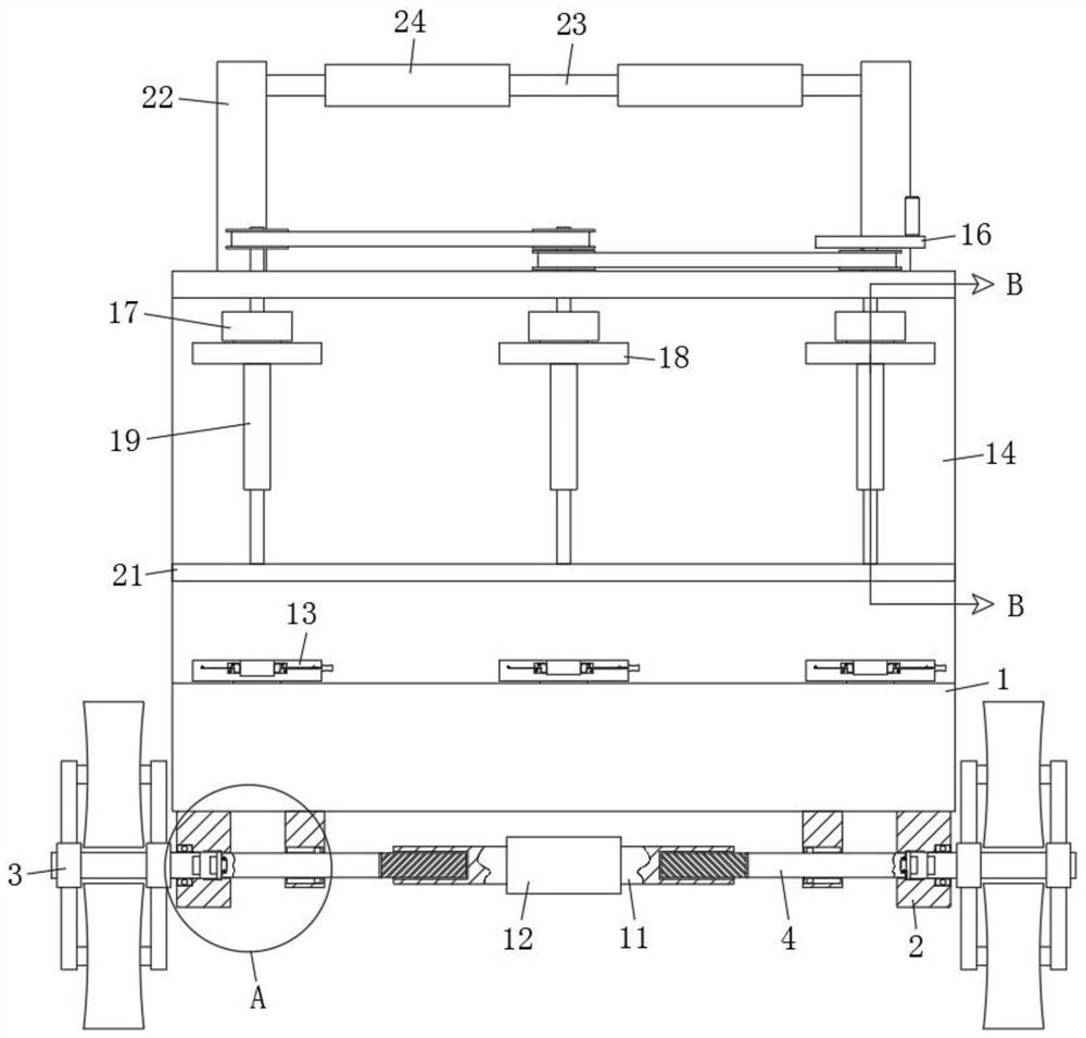
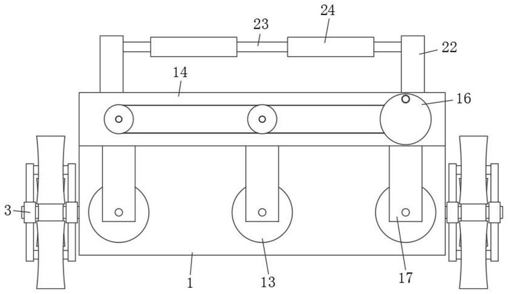
[0030] refer to figure 1 , 2 And 8, a cable reel moving device used by a ship-borne mobile emergency rejection vehicle, comprising a base 1, mounting blocks 2 are fixed on both sides of the bottom surface of the base 1, and mounting holes are provided on both sides of the mounting block 2, and the mounting holes One side of the inner wall is rotatably connected with a walking component 3 that can roll and climb. The positioning and release of the walking components 3 is performed through the locking component. When in use, the walking component 3 can switch between a single wheel and three wheels through the locking component Use, thereby make device realize the smooth walking of plane and uneven road surface, and then greatly improve the convenience when device travels, base 1 top front side also rotates to be used for propping up the support assembly 13 of cable reel, base 1 top rear The side is also fixed with an L-shaped plate 14, and the top surface of the L-shaped plate...
Embodiment 2
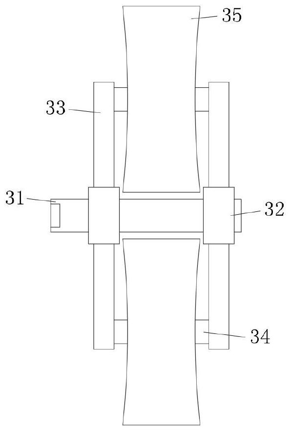
[0032] Such as Figure 1-3 As shown, this embodiment is basically the same as Embodiment 1. Preferably, the walking assembly 3 includes a mounting rod 31, and one end of the mounting rod 31 is rotatably connected to the inner wall of the mounting hole through a rolling bearing. Both ends of the mounting rod 31 are fixed with connecting blocks 32 , the outer wall of connecting block 32 is fixed with strip plate 33, and the two strip plates 33 of the same group are connected with driving rod 34 in rotation, and the outer wall of driving rod 34 is fixed with walking wheel 35, and strip plate 33 is equipped with three parallel Evenly distributed on the outer wall of the connecting block 32, six strip plates 33 are arranged in pairs.
[0033] In this embodiment, the walking component 3 is provided with three wheels, which can be rolled by a single wheel or alternately by three wheels when in use, so as to meet the convenience of walking on planes and steps.
Embodiment 3
[0035] Such as Figure 4 and 5 As shown, this embodiment is basically the same as Embodiment 1. Preferably, the deadlock assembly includes two locking rods 4, one end of the locking rod 4 extends into the mounting hole and is rotatably connected to a mounting post 5 at the end, and the mounting post 5 One end away from the lock rod 4 is fixed with a locking plate 6, the upper and lower sides of the locking plate 6 are fixed with a limit block 1, and the inner wall of the mounting hole is also provided with a limit slot 1, and the limit block 1 7 is all slidably connected in the limit slot 1 , the end of the locking plate 6 away from the mounting column 5 is also fixed with a locking part 8, the outer wall of the locking rod 4 is also provided with a limit sleeve 9, and the limit sleeve 9 is fixed on the bottom surface of the base 1, and the inner wall of the limit sleeve 9 is provided with a limit groove Two, the outer wall of the lock bar 4 is also fixed with a limit block 2...
PUM
 Abstract
Description
Claims
Application Information
 - R&D
- Intellectual Property
- Life Sciences
- Materials
- Tech Scout
- Unparalleled Data Quality
- Higher Quality Content
- 60% Fewer Hallucinations
Browse by: Latest US Patents, China's latest patents, Technical Efficacy Thesaurus, Application Domain, Technology Topic, Popular Technical Reports.
© 2025 PatSnap. All rights reserved.Legal|Privacy policy|Modern Slavery Act Transparency Statement|Sitemap|About US| Contact US: help@patsnap.com


