A kind of antiskid performance testing equipment for crawler production

A technology for anti-skid performance and testing equipment, which is applied in the direction of vehicle trackless testing, etc., can solve the problems of inconvenient sliding adjustment, increase the cost of use, etc., and achieve the effect of improving the scope of application

Active Publication Date: 2022-06-07
常州欧爱欧履带有限公司
View PDF3 Cites 0 Cited by
  • Summary
  • Abstract
  • Description
  • Claims
  • Application Information

AI Technical Summary

Problems solved by technology

[0004] In view of the above situation, in order to overcome the defects of the prior art, the present invention provides a kind of anti-skid performance testing equipment for crawler production, which effectively solves the problem that the road slippage simulated by the current test bench in the above-mentioned background technology is usually fixed, which is inconvenient. The slip is adjusted, and the distance between two adjacent rollers is fixed. When the distance between the two tracks is different, a different test bench needs to be replaced, which increases the cost of use.

Method used


Image

  • A kind of antiskid performance testing equipment for crawler production
  • A kind of antiskid performance testing equipment for crawler production
  • A kind of antiskid performance testing equipment for crawler production

Examples


Embodiment 1

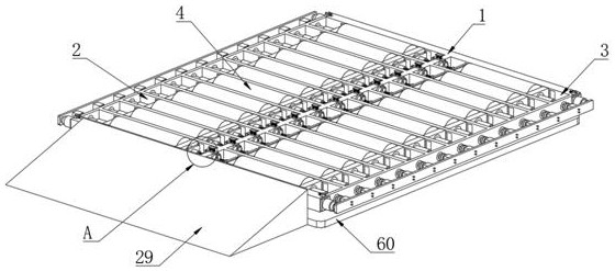
[0036] Example one, by Figure 1 to Figure 11 Given, the present invention includes an anti-slip performance support test table 1, the top of the anti-slip performance support test table 1 is provided with a number of first rectangular holes 2 and a number of second rectangular holes 3, the first rectangular hole 2 and the second rectangular hole 3 There are rollers 4 inside, and both ends of the rollers 4 are provided with supporting movable seats 5. Both ends of the rollers 4 are fixedly connected with a first fixed shaft 6 and a second fixed shaft 7. The first fixed shaft 6 and The second fixed shafts 7 respectively pass through the corresponding supporting movable bases 5 , and the first fixed shafts 6 and the second fixed shafts 7 are connected to the corresponding supporting movable bases 5 through the first bearings 8 respectively. The inner wall and the inner walls of both sides of the second rectangular hole 3 are respectively provided with two first sliding grooves 1...

Embodiment 2

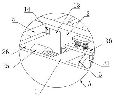
[0038] Embodiment 2, on the basis of Embodiment 1, by figure 1 , figure 2 and Figure 10 Given, the threaded anisotropic adjustment unit includes a fixed column 25 arranged at one end of the first fixed shaft 6, one end of the fixed column 25 is provided with a threaded groove 12 that is matched with the rotating bidirectional adjustment screw 10, and one side of the fixed column 25 is provided with There is a first movable adjustment plate 26, a second through hole 27 is opened on one side of the first movable adjustment plate 26, the fixed column 25 penetrates through the second through hole 27, and the fixed column 25 and the inner wall of the second through hole 27 are fixedly connected, One end of the first movable adjusting plate 26 is connected with the side supporting the movable seat 5 through two supporting columns 28;

[0039] According to the distance between the two tracks, the rotating bidirectional adjusting screw 10 is driven to rotate, and the two fixed col...

Embodiment 3

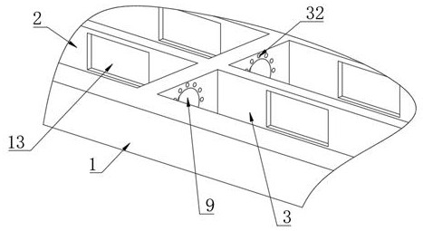
[0040] Embodiment 3, on the basis of Embodiment 1, by figure 1 , figure 2 , image 3 , Figure 7 and Figure 8Given, two movable limit and anti-rotation rings 31 are sleeved on the outside of the rotating two-way adjusting screw 10, and a plurality of first limit grooves 32 are opened on one side of the inner wall of the first rectangular hole 2 and the second rectangular hole 3, A plurality of first limit posts 33 are fixedly connected to the adjacent sides of two adjacent movable limit and anti-rotation rings 31, and two limit holes 34 are opened on one side of the movable limit and anti-rotation rings 31, and the limit The inner wall of one side of the hole 34 is communicated with the inner wall of the movable limit and anti-rotation ring 31. Four limit bars 35 are fixedly connected to the rotating two-way adjusting screw 10, and the top of the anti-slip performance support test table 1 is provided with several second The movable adjustment plate 36 is provided with a ...


PUM


Abstract

The invention relates to the technical field of track production testing equipment, and discloses an anti-skid performance testing device for track production, which solves the inconvenience of adjusting the slip, and the distance between two adjacent rollers is fixed. When the distance between the two tracks is different, different test benches need to be replaced, which increases the cost of use. It includes the anti-skid performance support test bench, and the top of the anti-skid performance support test bench is provided with a number of first A rectangular hole and several second rectangular holes, rollers are arranged in the first rectangular hole and the second rectangular hole, the two ends of the rollers are provided with supporting movable seats, and the two ends of the rollers are respectively fixedly connected with the first fixed shaft and the second fixed shaft; it is convenient to adjust the distance between two adjacent rollers, so that both crawlers can be located on the rollers, which improves the scope of application, and can adjust the resistance to the rotation of the rollers, so as to simulate the crawler tractor in the Use on different slippery road surfaces.

Description

technical field [0001] The invention belongs to the technical field of crawler belt production testing equipment, in particular to an anti-skid performance testing equipment used for crawler belt production. Background technique [0002] Crawler tractor is a kind of tractor, which has the advantages of low pressure per unit area of ​​soil and good adhesion to soil. In the production of crawler tractors, it is necessary to test the anti-skid performance of the crawler tractors produced. The anti-skid performance of the crawler is usually tested on a test bench. [0003] At present, the road surface slippage simulated by the test bench is usually fixed, which is inconvenient to adjust the slippage, and the distance between two adjacent rollers is fixed. When the distance between the two tracks is different, it is necessary to replace different The test bench increases the cost of use. SUMMARY OF THE INVENTION [0004] In view of the above situation, in order to overcome th...

Claims


Application Information

Patent Timeline
Patent Type & Authority Patents(China)
IPC IPC(8): G01M17/03
CPCG01M17/03
Inventor 简宗贤
Owner 常州欧爱欧履带有限公司
Why Eureka
Try Eureka