
Rock sheet true three-direction collapse test device and method
A test device and thin plate technology, applied in the direction of testing material strength by applying a stable bending force, can solve the difference in shape between beam and rock thin plate samples, fail to realize true three-dimensional loading of rock thin plate samples, and rock bending The law of deformation and failure cannot be directly used to evaluate problems such as layered rock mass
- Summary
- Abstract
- Description
- Claims
- Application Information
AI Technical Summary
Problems solved by technology
Method used
Image

Examples
Embodiment Construction
[0028] The present invention will be further described in detail below in conjunction with the accompanying drawings and specific embodiments.
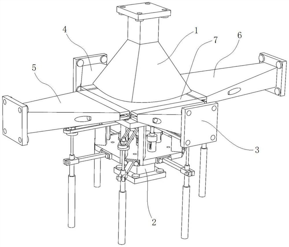
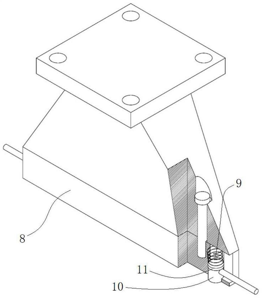
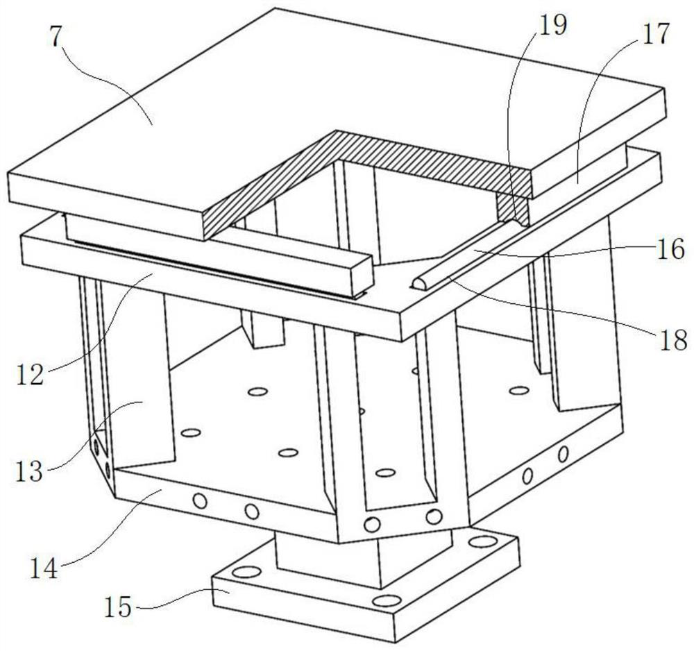
[0029] Such as Figure 1~6 As shown, a true three-way buckling test device for rock thin plates includes a spherical indenter 1, a frame-type support base 2, a front indenter 3, a rear indenter 4, a left indenter 5 and a right indenter 6; The spherical indenter 1 is located directly above the frame-type support base 2, and the rock thin-plate sample 7 is horizontally located between the spherical indenter 1 and the frame-type support base 2; The side elevation is facing; the rear indenter 4 is facing the rear side elevation of the rock thin plate sample 7; the left indenter 5 is facing the left side elevation of the rock thin plate sample 7; The right indenter 6 is directly opposite to the right side elevation of the rock thin plate sample 7; the loading surfaces of the front indenter 3, the rear indenter 4, the left indenter 5 and t...
PUM
 Abstract
Description
Claims
Application Information