Cable clamp with protection effect

A cable fixture and protection effect technology, applied in electrical components, instruments, alarms, etc., can solve the problems of no shedding warning, safety hazards, and small cable outer diameter range, so as to reduce safety hazards, increase life, and disassemble Quick and easy effects

Pending Publication Date: 2022-04-26
刘海兵
View PDF1 Cites 0 Cited by
  • Summary
  • Abstract
  • Description
  • Claims
  • Application Information

AI Technical Summary

Problems solved by technology

[0005] The purpose of the present invention is to provide a cable clamp with a protective effect in order to solve the above problems, which solves the problem of adapting to the different deviations of the outer diameter of the cable by reserving a certain angle at both ends of the two arc-shaped brackets, but the cables that can be adapted The outer diameter range is small, and there is no fall-off warning function, which has great safety hazards when the connectors are used for a long time and loosen.

Method used


Image

  • Cable clamp with protection effect
  • Cable clamp with protection effect
  • Cable clamp with protection effect

Examples


Embodiment Construction

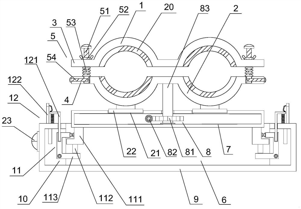
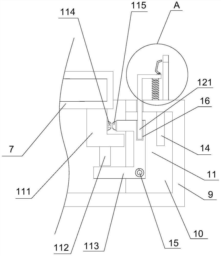
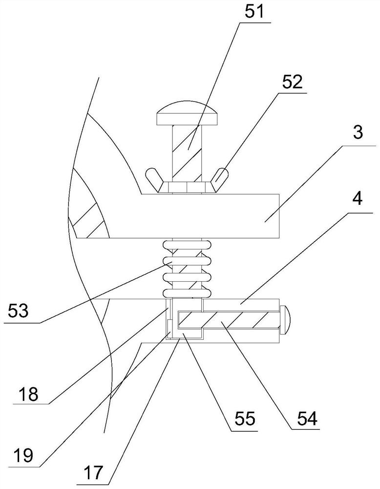
[0028] like Figure 1-5 As shown, this specific embodiment adopts the following technical solutions: a cable clamp with a protective effect, including an upper clamp 1 and a lower clamp 2, the upper clamp 1 is relatively arranged above the lower clamp 2, and the upper clamp 1 Both ends are welded with an upper side plate 3, both ends of the lower fixture 2 are welded with a lower side plate 4, and a fixing mechanism 5 is arranged between the upper side plate 3 and the lower side plate 4 on both sides. The fixing mechanism 5 includes a first bolt 51 and a first spring 53, and the first spring 53 is sleeved on the surface of the first bolt 51, and a connecting plate 7 is arranged below the lower clamp 2, and the connecting plate 7 It is a hollow structure, and the connecting plate 7 is provided with an adjusting mechanism 8 inside, and the adjusting mechanism 8 includes a worm wheel 81, and one side of the worm wheel 81 is meshed with a worm 82, and a fixing seat 9 is arranged u...


PUM


Abstract

The cable clamp with the protection effect comprises an upper clamp and a lower clamp, the upper clamp is oppositely arranged above the lower clamp, upper side plates are welded to the two ends of the upper clamp, lower side plates are welded to the two ends of the lower clamp, and fixing mechanisms are arranged between the upper side plates and the lower side plates on the two sides. The cable clamp comprises an upper clamp and a lower clamp, fixing mechanisms are arranged on the upper clamp and the lower clamp, each fixing mechanism comprises a first bolt and a first spring, the first springs are connected to the surfaces of the first bolts in a sleeving mode, and a connecting plate is arranged below the lower clamp. The cable clamp has the beneficial effects that the fixing mechanisms are arranged, and a cable can be clamped between the upper clamp and the lower clamp by rotating butterfly nuts of the fixing mechanisms; when cables with different diameters are fixed, the butterfly nut can be twisted according to the sizes of the cables for adjustment, the adjustment is very convenient and suitable for a large outer diameter range of the cables, meanwhile, the bottom block at the lower end of the first bolt is fixed by the second bolt, the first bolt can be stably fixed, and the limiting of the first bolt can be relieved by detaching the second bolt.

Description

Technical field: [0001] The invention belongs to the technical field of cable fixing equipment, in particular to a cable clamp with protective effect. Background technique: [0002] Cables are wires used to transmit electric energy. They are widely used in electrical equipment, lighting circuits, and household appliance circuits. When installing cables, they need to be installed on the fixing seats on the wall through clamps to avoid the risk of electric shock and leakage caused by scattering. [0003] Under the existing technology, in a cable clamp and cable installation device with the patent number CN201810048417.3, a certain included angle is reserved at both ends of the two arc-shaped brackets to adapt to different deviations in the outer diameter of the cable, but the cables that can be adapted The outer diameter range is small, and there is no fall-off warning function, which poses a great safety hazard when the connector is used for a long time and becomes loose; ...

Claims


Application Information

Patent Timeline
IPC IPC(8): H02G3/32G08B21/24
CPCH02G3/32G08B21/24
Inventor 刘海兵
Owner 刘海兵
Why Eureka
Try Eureka