Control method of driving circuit, driving circuit and light-emitting substrate

A technology of drive circuit and control method, applied in the direction of circuits, electrical components, electric solid devices, etc., can solve the problems of increasing reactive power loss, unable to adjust power supply voltage, etc., and achieve the effect of reducing backlight power consumption

Pending Publication Date: 2022-04-26
BOE TECH GRP CO LTD +1
View PDF0 Cites 1 Cited by
  • Summary
  • Abstract
  • Description
  • Claims
  • Application Information

AI Technical Summary

Problems solved by technology

In the related technology, Mini LED can adopt Active Matrix (AM) backlight driving method, and AM driving method usually uses multiple small-sized driver chips to respectively drive the corresponding mini LEDs. Due to the limitation of pins, the power supply voltage VLED cannot be adjusted, so the power supply voltage VLED can only be provided to the mini LED by a constant voltage method, which increases some reactive power losses.

Method used


Image

  • Control method of driving circuit, driving circuit and light-emitting substrate
  • Control method of driving circuit, driving circuit and light-emitting substrate
  • Control method of driving circuit, driving circuit and light-emitting substrate

Examples


Embodiment Construction

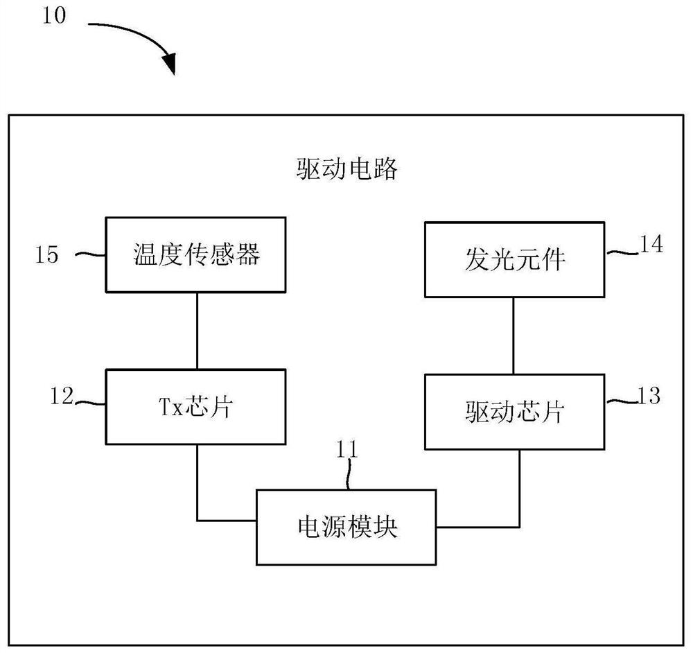
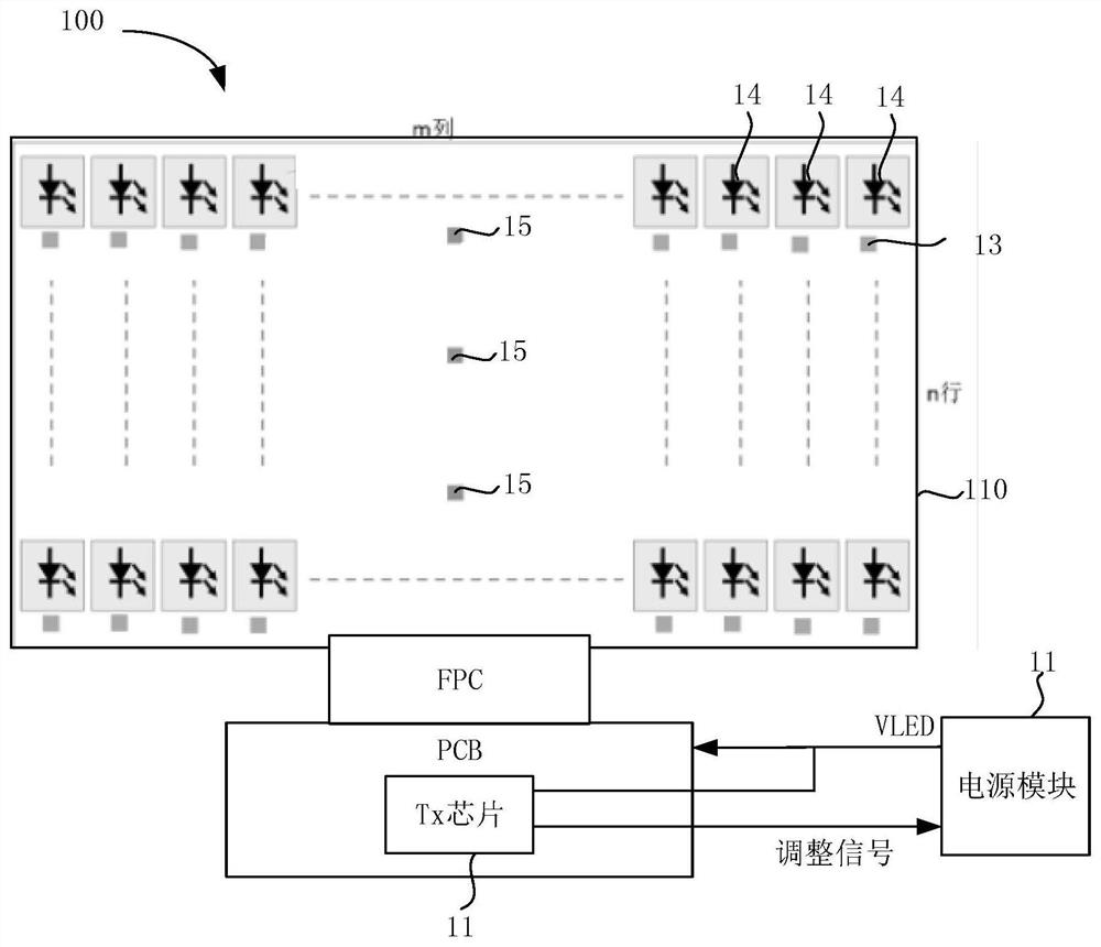
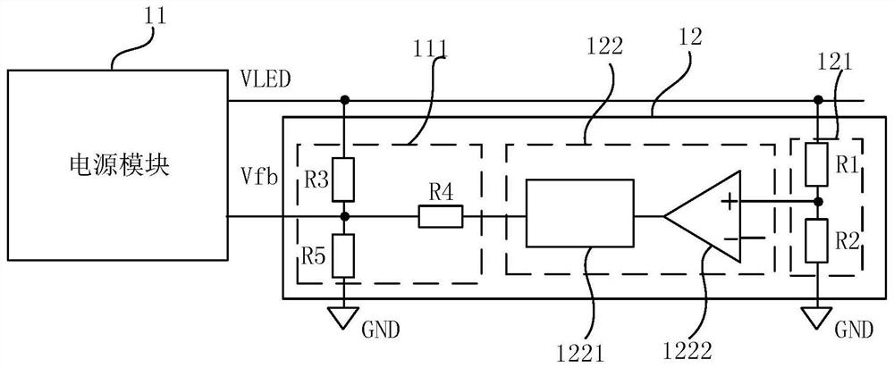
[0053] Embodiments of the present application are described in detail below, examples of which are shown in the drawings, wherein the same or similar reference numerals denote the same or similar elements or elements having the same or similar functions throughout. The embodiments described below by referring to the figures are exemplary, are only for explaining the present application, and should not be construed as limiting the present application.

[0054]In the description of the present application, it should be understood that the terms "center", "longitudinal", "transverse", "length", "width", "thickness", "upper", "lower", "front", " Orientation indicated by rear, left, right, vertical, horizontal, top, bottom, inside, outside, clockwise, counterclockwise, etc. The positional relationship is based on the orientation or positional relationship shown in the drawings, which is only for the convenience of describing the application and simplifying the description, and does...


PUM


Abstract

The invention discloses a control method of a driving circuit, the driving circuit and a light-emitting substrate. The driving circuit is used for a light-emitting substrate, and the control method comprises the following steps: obtaining a wiring voltage drop voltage, a lamp string voltage, a lamp string voltage difference and a channel voltage of the light-emitting substrate, calculating to obtain a target power supply voltage, comparing the target power supply voltage with a power supply output voltage, and generating an adjustment signal according to a comparison result of the power supply output voltage and the target power supply voltage, and adjusting the power supply output voltage according to the adjusting signal so as to match the power supply output voltage with the target power supply voltage. According to the control method, the power supply voltage required by the light-emitting substrate is obtained by obtaining the routing voltage drop voltage, the lamp string voltage, the lamp string voltage difference and the channel voltage, so that the power supply output voltage can be adjusted to be matched with the power supply voltage. Therefore, reactive power loss can be prevented from being increased, and the purpose of reducing backlight power consumption is achieved.

Description

technical field [0001] The present application relates to the field of display technology, in particular to a control method of a driving circuit, a driving circuit and a light-emitting substrate. Background technique [0002] Mini LED can achieve finer backlight adjustment, so as to achieve better HDR effect. In the related technology, Mini LED can adopt Active Matrix (AM) backlight driving method, and AM driving method usually uses multiple small-sized driver chips to drive the corresponding mini LEDs respectively. Due to the limitation of pins, the power supply voltage VLED cannot be adjusted, and the power supply voltage VLED can only be provided to the mini LED by a constant voltage method, which increases some reactive power losses. Contents of the invention [0003] This application aims to solve at least one of the technical problems existing in the prior art. Therefore, the present application needs to provide a control method of a driving circuit, a driving cir...

Claims


Application Information

Patent Timeline
Patent Type & Authority Applications(China)
IPC IPC(8): H05B45/30G09G3/32G09G3/34H05B45/50H05B47/165
CPCH05B45/30H05B45/50H05B47/165G09G3/32G09G3/3406H05B45/14H05B45/18H05B45/46H01L25/0753H01L33/62
Inventor 郝卫时凌云黄文杰王飞飞苏文刚石蕊商兴策张峻玮尹凯民谷其兵贾丽丽王秀荣
Owner BOE TECH GRP CO LTD
Why Eureka
Try Eureka