

Lightning protection post insulator dip-coating equipment for power transmission line
A technology for pillar insulators and transmission lines, which is applied in the field of dip coating equipment for lightning protection pillar insulators for transmission lines, can solve problems such as the influence of protective liquid coating, and achieve the effect of strengthening the fixing effect
- Summary
- Abstract
- Description
- Claims
- Application Information
AI Technical Summary
Problems solved by technology
Method used
Image

Examples
Embodiment 1
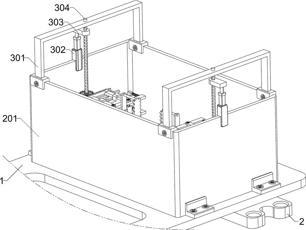
[0041] Dipping equipment for lightning protection post insulators for transmission lines, according to Figure 1-3 As shown, it includes a bottom plate 1 and a mounting clip 2; two mounting clips 2 are fixedly connected to the front part of the lower surface of the bottom plate 1 and the rear part of the lower surface; it also includes a fixing unit, a disturbance dipping unit and a power unit; The surface is connected with a fixed unit; the right part of the upper surface of the bottom plate 1 is connected with a disturbance dipping unit; the front and rear of the disturbance dipping unit are connected with a power unit.
[0042] Working process: Before using the dip-coating equipment for lightning-proof post insulators for transmission lines, hereinafter referred to as the insulator dip-coating equipment, first install the insulator dip-coating equipment in the processing workshop of lightning-proof post insulators, connect the external power supply, and then the operator con...
Embodiment 2
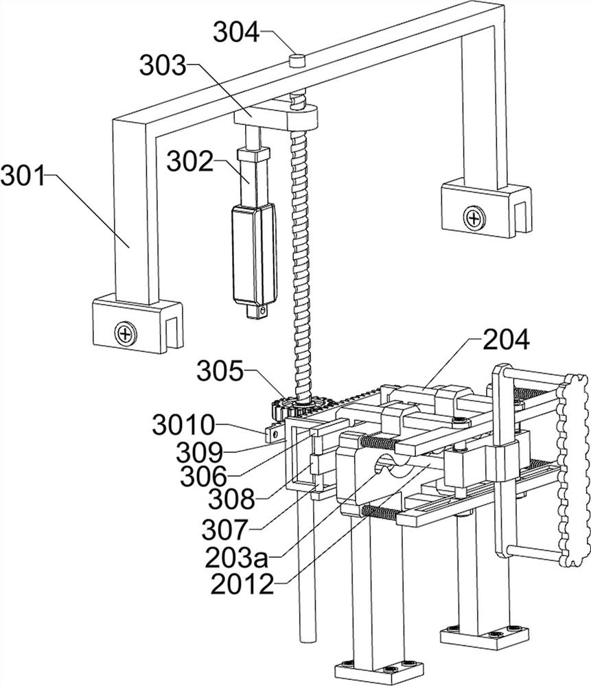
[0044] On the basis of Example 1, according to figure 1 and Figure 4-6 As shown, the fixed unit includes a first gantry 101, a first connecting rod 102, a first electric slide rail 103, a mounting block 104, a first electric actuator 105, a connecting ear 106, a ring frame 107, a second electric slide Rail 108, second gantry 109, electric rope retractor 1010, soft rope 1011, deflector 1012, electric sliding block 1013, U-shaped bar 1014, first fixing clip 1015, conduit 1016 and second fixing clip 1017; A first gantry 101 is connected by bolts on the left part of the upper surface and the right part of the upper surface of the bottom plate 1; two first connecting rods 102 are connected by bolts on the upper parts of the two first gantry frames 101; two first connecting rods 102 Each of the lower surfaces is equipped with a first electric slide rail 103; each of the two first electric slide rails 103 is slidably connected with a mounting block 104 through an electric slider; e...
Embodiment 3
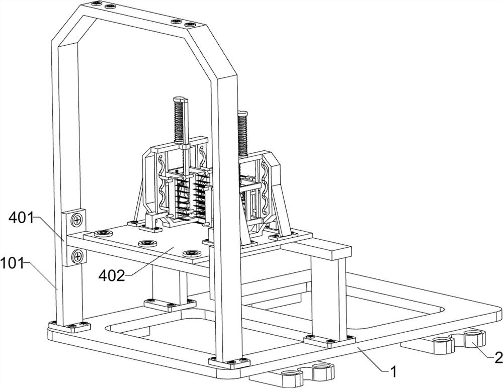
[0055] On the basis of Example 2, according to figure 1 and Figure 13-16As shown, it also includes a vibration type dust removal unit; the middle part of the upper surface of the bottom plate 1 is connected with a vibration type dust removal unit; the left part of the fixed unit is connected with the vibration type dust removal unit; Shaped frame 403, support frame 404, second horizontal plate 405, second elastic member 406, second rack 407, vertical plate 408, transmission rod 409, second gear 4010, third rack 4011, second U-shaped frame 4012, the third slide bar 4013, the hair brush 4014, the positioning rod 4015 and the limit column 4016; the middle part of the upper surface of the base plate 1 is bolted to an L-shaped frame 401; the left part of the L-shaped frame 401 is bolted to the first portal frame 101; The upper surface of the L-shaped frame 401 is bolt-connected with a bearing plate 402; the upper surface front and the upper surface rear of the bearing plate 402 a...
PUM
 Abstract
Description
Claims
Application Information