Automatic filling device of timber slicing machine
An automatic filler and slicer technology, which is applied in the manufacture of thin wood chips, wood processing equipment, manufacturing tools, etc., can solve the problems of easy to scratch the conveyor belt, affect the cutting accuracy, and poor wood smoothness, etc., so as to improve the service life, Reduce the loss of resources and avoid the effect of pulling damage
- Summary
- Abstract
- Description
- Claims
- Application Information
AI Technical Summary
Problems solved by technology
Method used
Image
Examples
Embodiment 1
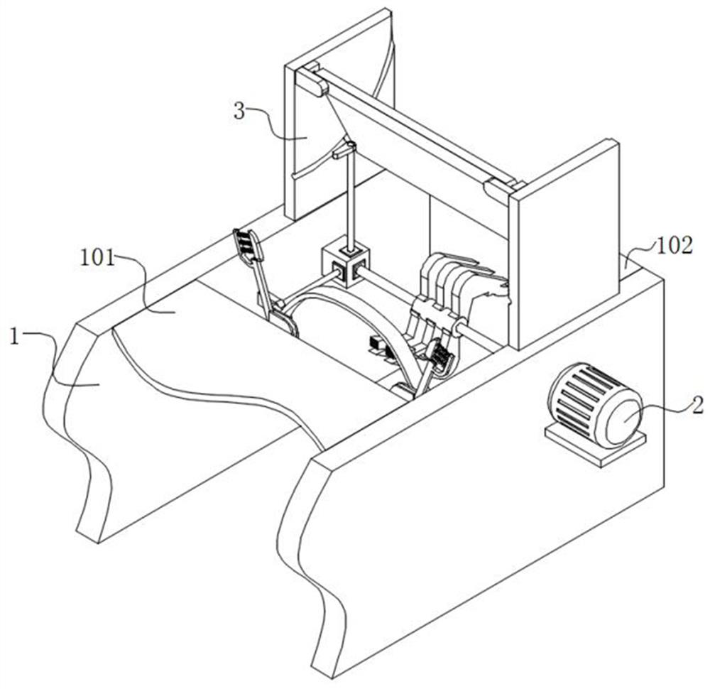
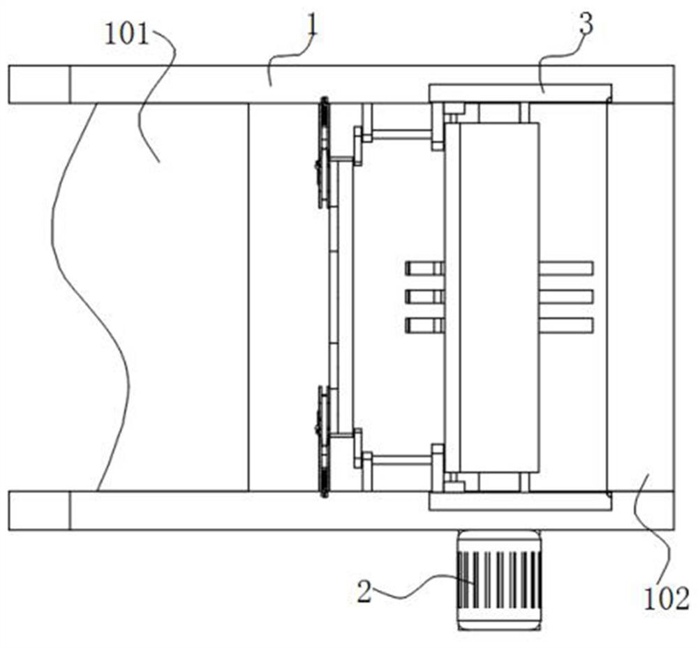
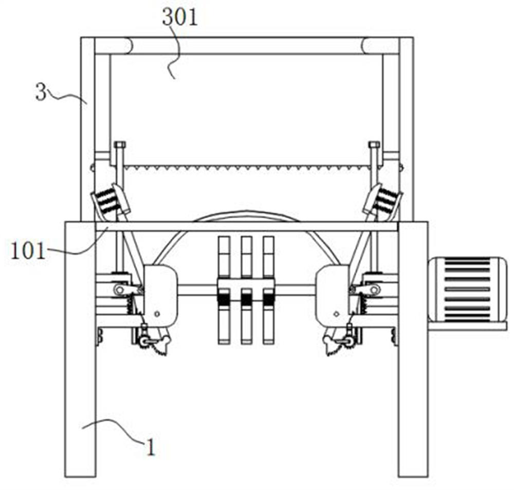
[0049] Embodiment 1: as Figure 1 to Figure 4 As shown, the automatic filling device of the wood slicer in this embodiment includes a machine platform 1, a conveyor belt body 101 installed on the top of the machine platform 1, and a slice feeding place 102 at the edge of the machine platform 1, and one side of the machine platform 1 A servo motor 2 is installed on the surface, and a steering gear box 203 is installed on the inner surface of the machine table 1, and a drive shaft 204 is installed between two groups of steering gear boxes 203, and one end of the drive shaft 204 is connected to the servo motor 2. The output shaft on one side of the steering gear box 203 is equipped with an anti-tear mechanism, and the surface of the machine 1 on the side of the anti-tear mechanism is equipped with a position adjustment mechanism, and the top output of the steering gear box 203 A feeding mechanism is installed on the shaft, and a filling mechanism is installed on the drive shaft 2...
Embodiment 2
[0052] Embodiment 2: on the basis of embodiment 1: further, as Figure 5 , Figure 6 and Figure 12 As shown, the anti-tear mechanism includes a first deflection block 4 and a tough metal plate 401. The output shaft on one side of the steering gear box 203 is equipped with a first deflection block 4, and the movable parts of the first deflection block 4 are jointly installed. ductile sheet metal 401 .
[0053] When working: if Figure 5 , Figure 6 and Figure 12 As shown, on the basis that the servo motor 2 drives the drive shaft 204 to rotate, the rotation of the drive shaft 204 drives the transmission of the internal helical gear of the steering gear box 203, and the helical gear on the side of the steering gear box 203 is equipped with a first deflection block 4 through the shaft , that is, the rotation of the drive shaft 204 drives the first deflection block 4 to rotate synchronously, and the rotation of the drive shaft 204 drives the flexible metal plate 401 install...
Embodiment 3
[0054] Embodiment 3: on the basis of embodiment 2: further, as Figure 7 and Figure 8 As shown, the position adjustment mechanism includes an assembly frame 5, a wedge tooth plate 6, a guide gear 7, a timber adjustment member 501 and movable parts, and the surface of the machine platform 1 on the side of the first deflection block 4 is equipped with an assembly frame 5, and the assembly frame The surface of 5 is provided with a chute, and the inside of the chute is slidably equipped with a wedge tooth plate 6, and the bottom end of the assembly frame 5 is equipped with a guide gear 7, and the bottom end of the assembly frame 5 is also equipped with a wood adjusting part 501 through a rotating shaft, and the wedge The top of the block tooth plate 6 is located on the rotation path of the first deflection block 4, and the wedge block tooth plate 6 is used in conjunction with the guide gear 7, and the guide gear 7 is used in conjunction with the wood adjustment part 501, and the ...
PUM
 Abstract
Description
Claims
Application Information
 - R&D
- Intellectual Property
- Life Sciences
- Materials
- Tech Scout
- Unparalleled Data Quality
- Higher Quality Content
- 60% Fewer Hallucinations
Browse by: Latest US Patents, China's latest patents, Technical Efficacy Thesaurus, Application Domain, Technology Topic, Popular Technical Reports.
© 2025 PatSnap. All rights reserved.Legal|Privacy policy|Modern Slavery Act Transparency Statement|Sitemap|About US| Contact US: help@patsnap.com


