
Logistics distribution device based on logistics distribution tool and limiting self-locking structure

A technology of logistics distribution and self-locking structure, which is applied to trolley accessories, transportation and packaging, multi-axis trolleys, etc., can solve the problems that the driving mechanism cannot be linked and combined with synchronous drive, and the operation is troublesome and inconvenient, so as to save manual operation, Good anti-drop protection and simplified retraction operation steps

Active Publication Date: 2022-04-29
NANJING POLYTECHNIC INSITUTE
View PDF4 Cites 0 Cited by
  • Summary
  • Abstract
  • Description
  • Claims
  • Application Information

AI Technical Summary

Problems solved by technology

[0004] The object of the present invention is to provide a logistics distribution device with a position-limiting self-locking structure based on logistics distribution, so as to solve the problem that most of the driving mechanisms of the multiple barrier components proposed in the background technology cannot be linked and synchronously driven, and need to be operated step by step and multiple times Only then can all the barrier components be retracted, and the operation and use are troublesome and inconvenient

Method used


Image

  • Logistics distribution device based on logistics distribution tool and limiting self-locking structure
  • Logistics distribution device based on logistics distribution tool and limiting self-locking structure
  • Logistics distribution device based on logistics distribution tool and limiting self-locking structure

Examples


Embodiment Construction

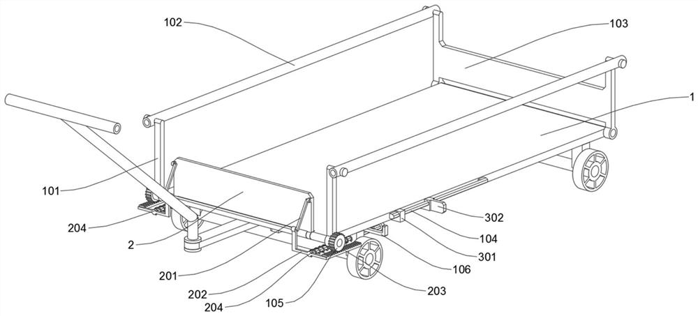
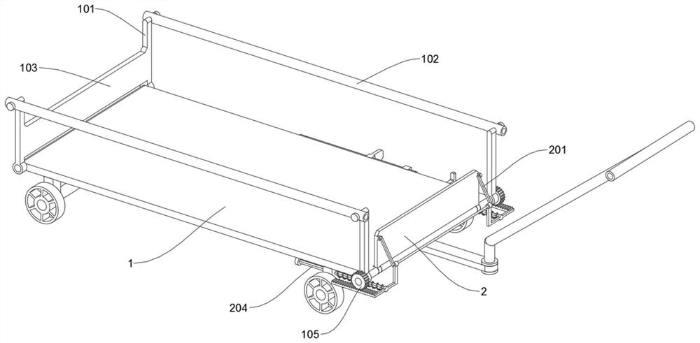
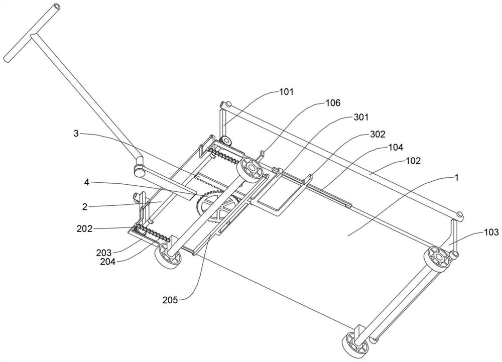
[0027] The technical solutions in the embodiments of the present invention will be clearly and completely described below with reference to the accompanying drawings in the embodiments of the present invention. Obviously, the described embodiments are only new aspects of the present invention.

[0028] Some examples of the type, but not all of the examples.

[0029] see Figure 1 to Figure 5 , an embodiment provided by the present invention: a logistics distribution device with a limit self-locking structure based on logistics distribution, including a tray 1; the tray 1 has a rectangular structure as a whole, and its bottom is symmetrically welded with four protruding installation blocks in front and rear corresponding to left and right sides, Two laterally supported axles are symmetrically welded on the four protruding mounting blocks, and four wheels are symmetrically sleeved at the left and right ends of the two axles; a strip-shaped traction plate is welded at the middle ...


PUM


Abstract

The invention discloses a logistics distribution device based on a limiting self-locking structure of a logistics distribution tool, relates to the technical field of logistics transfer devices, and solves the problems that most of driving mechanisms of multiple barrier assemblies of an existing logistics distribution device cannot be linked, combined and synchronously driven, all the barrier assemblies can be folded and unfolded only through step-by-step and multi-time operation, and the use cost is high. And operation and use are troublesome, strenuous and inconvenient. The invention discloses a logistics distribution device based on a logistics distribution tool limiting self-locking structure. The logistics distribution device comprises a tray; the whole tray is of a rectangular structure, four protruding installation blocks are welded to the bottom of the tray in a front-back corresponding left-right symmetry mode, two transversely-supported wheel shafts are symmetrically welded to the four protruding installation blocks, and the left ends and the right ends of the two wheel shafts are symmetrically sleeved with four wheels. A strip-shaped traction plate is welded to the middle position of the bottom of the front end of the tray. According to the device, the trouble of carrying out folding and unfolding operation on multiple barrier mechanisms of the device step by step and step by step can be omitted, and the folding and unfolding operation steps of the barrier limiting mechanism of the device are simplified.

Description

technical field [0001] The invention relates to the technical field of logistics transfer devices, in particular to a logistics distribution device with a position-limiting self-locking structure based on logistics distribution. Background technique [0002] In the logistics system of fresh food distribution, the first step is to transfer and load the cargo baskets inside the warehouse. [0003] In order to implement a more comprehensive blocking and limiting of the cargo basket in the existing logistics distribution devices, most of them need to set up multiple barrier components to be used together. However, because the driving mechanisms of the multiple barrier components cannot be linked and combined with synchronous driving, it is necessary to step by step, It takes several operations to perform expansion and contraction of all the barrier components, which is laborious and inconvenient to operate, and most of the barrier components need to be bent over and attached to ...

Claims


Application Information

Patent Timeline
IPC IPC(8): B62B3/02B62B5/00
CPCB62B3/02B62B5/00
Inventor 卜苏华赵军晏自翔
Owner NANJING POLYTECHNIC INSITUTE
Learn More