Photographic fixing apparatus, temperature-controlling method and image forming apparatus

A temperature control method and a technology for fixing temperature, which are applied to electric heating devices, electric recording technology using charge patterns, and equipment for electric recording technology using charge patterns, etc., which can solve problems such as lifespan reduction, deterioration, and poor thermal response performance

Inactive Publication Date: 2004-03-31
KK TOSHIBA
View PDF0 Cites 0 Cited by
  • Summary
  • Abstract
  • Description
  • Claims
  • Application Information

AI Technical Summary

Problems solved by technology

However, in order to improve the image quality, the fixing roller used in the full-color fixing device uses a rubber roller, and the thermal response performance of the rubber roller is inferior to that of the hard roller. The temperature is fixed, and when

Method used


Image

  • Photographic fixing apparatus, temperature-controlling method and image forming apparatus
  • Photographic fixing apparatus, temperature-controlling method and image forming apparatus
  • Photographic fixing apparatus, temperature-controlling method and image forming apparatus

Examples


Embodiment Construction

[0021] Hereinafter, an embodiment of the present invention will be described with reference to the drawings.

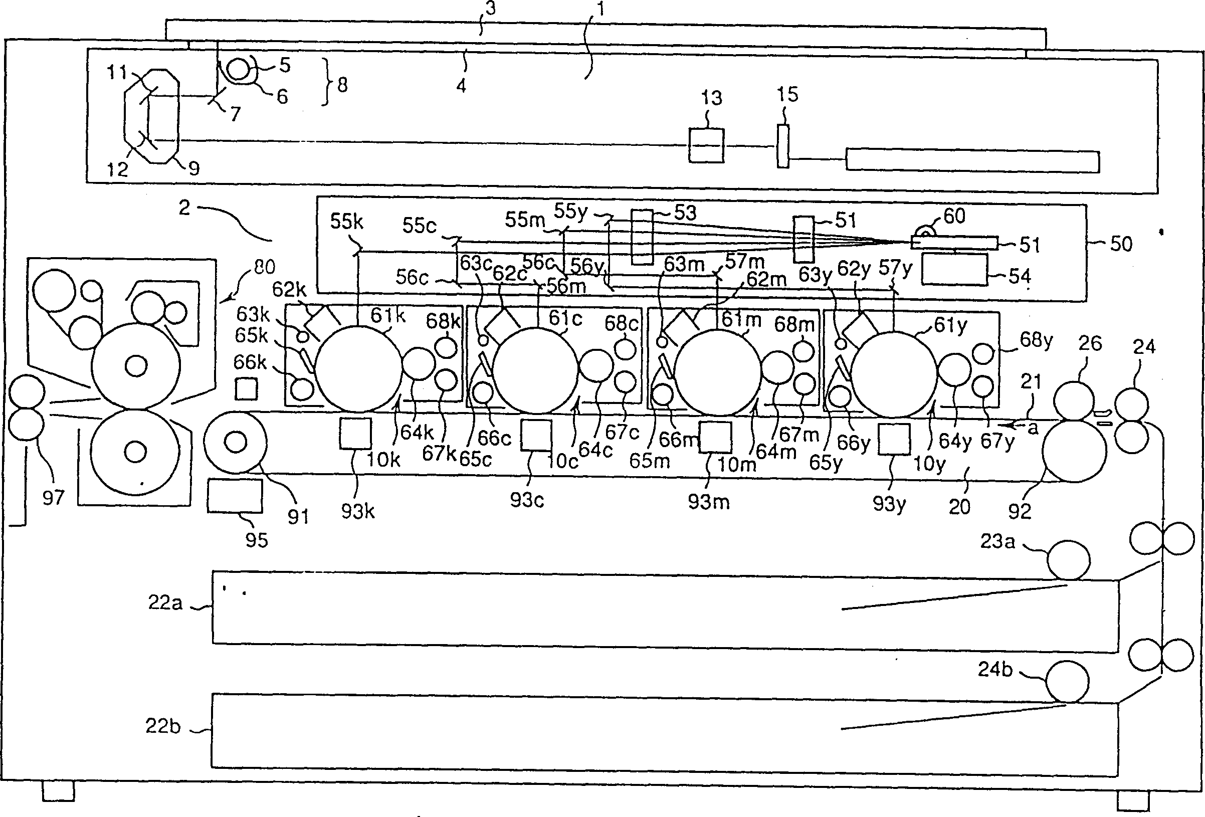
[0022] figure 1 It is a schematic configuration diagram of a full-color copier related to the image forming apparatus of the present invention. A full-color copier is composed of a scanner section 1 as a reading device and a printer section 2 as an image forming device.

[0023] The scanning unit 1 for reading the image of the document has a document table cover 3 on its upper part, and has a document table made of transparent glass for placing the document D opposite to the closed document table cover 3 4. Below the original table 4, an exposure lamp 5 for illuminating the original D placed on the original table 4, a reflector 6 for converging the light of the exposure lamp 5 on the original D, and light from the original D are provided. The reflected light turns to the left in the figure to the first reflector 7 and the like. In addition, these exposure lamps 5 ...


PUM


Abstract

A microcomputer control section (76) is such that, when switching is mode from a pain sheet mode to a sheetboard/OHP mode by the operation of a corresponding keys (43) on an operation panel (40), the microcomputer control section changes the control temperature of an upper roller (81) to an equivalent bit value so as to vary that control temperature from 150 DEG C to 160 DEG C during which time the microcomputer control section, confirming the surface temperature of an upper roller (81) from a detection signal of a sensing section (73) through an A/D conversion section (77), turns an upper lamp heater (71) ON through a lamp control section (75) if the surface temperature of the upper roller is below 155 DEG C and, effecting continued confirmation of the surface temperature of the upper roller (81) from the detection signal of the sensing section (73) through the A/D conversion section (77), turns the upper lamp heater (71) OFF through the lamp control section (75) when the surface temperature of the upper roller (81) increases above 160 DEG C, so that a sheetboard/OHP sheet-ready (copyable) state is displayed on a liquid-crystal display section (42) on an operation panel (40).

Description

technical field [0001] The present invention relates to a fixing device having a fixing temperature switching mechanism, a method for controlling the temperature of the fixing device, and an image forming device such as an electronic copier having the fixing device. Transfers the toner image corresponding to the image read from (for example) the original to the supplied paper, and the above-mentioned fixing temperature switching mechanism uses a heating method that pressurizes and conveys the paper on which the toner image is transferred. Roller that fixes the toner image on the paper. Background technique [0002] Conventionally, in an image forming apparatus such as an electronic copier, an exposure lamp is used to irradiate an original placed on an original glass table (original placement table), and the reflected light of this exposure scanning is guided to form a pattern corresponding to the original on the photoconductor drum. The latent image is developed by adding t...

Claims


Application Information

Patent Timeline
IPC IPC(8): F16C13/00G03G15/20H05B3/00
CPCG03G15/2078G03G2215/00497G03G15/2039G03G15/2046
Inventor 山内真
Owner KK TOSHIBA
Why Eureka
Try Eureka